
How to Use SN74HCT08N: Examples, Pinouts, and Specs
 Design with SN74HCT08N in Cirkit Designer
Introduction
The SN74HCT08N, manufactured by Texas Instruments, is a quad 2-input AND gate that operates using high-speed CMOS technology. This component is designed to provide low power consumption while maintaining compatibility with TTL logic levels. It is widely used in digital circuits for performing logical AND operations on two input signals.
Explore Projects Built with SN74HCT08N
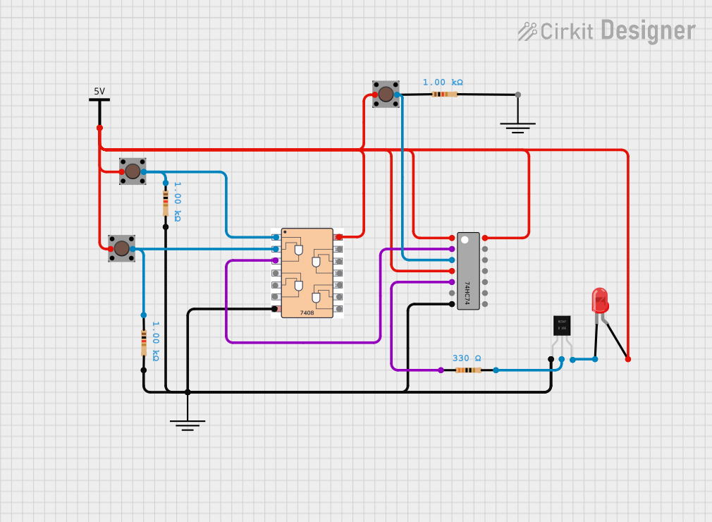 Open Project in Cirkit Designer
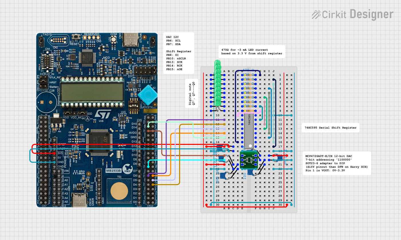 Open Project in Cirkit Designer
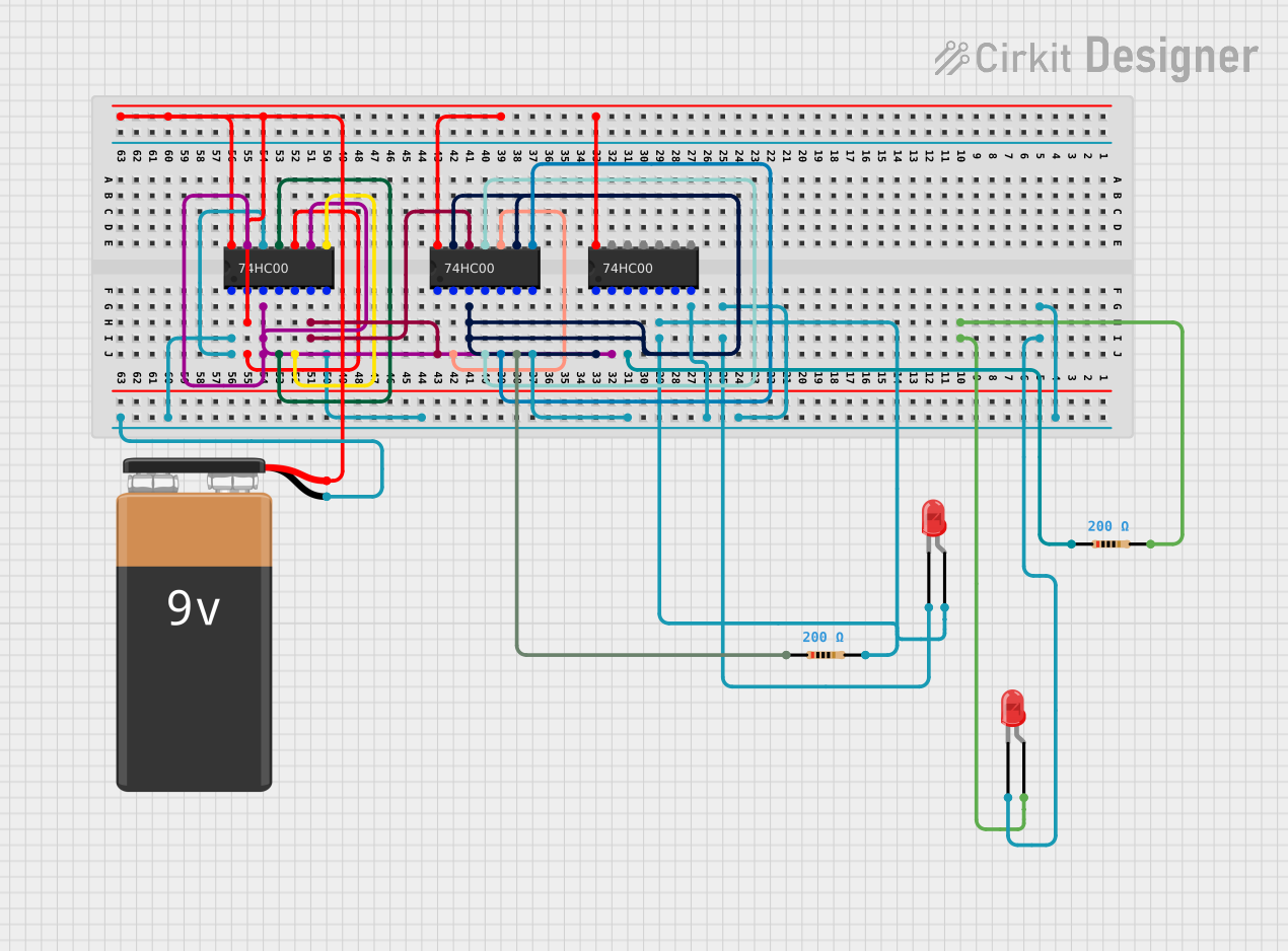 Open Project in Cirkit Designer
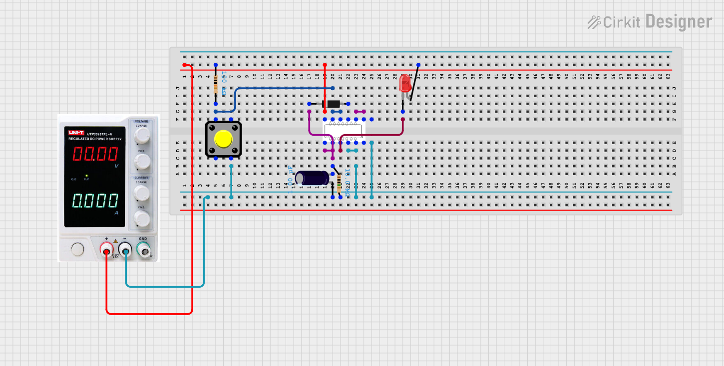 Open Project in Cirkit Designer
Explore Projects Built with SN74HCT08N
Open Project in Cirkit DesignerOpen Project in Cirkit DesignerOpen Project in Cirkit DesignerOpen Project in Cirkit DesignerCommon Applications and Use Cases
- Digital signal processing
- Logic control circuits
- Data routing and multiplexing
- Arithmetic and logic units (ALUs)
- Embedded systems and microcontroller-based projects
Technical Specifications
The following table outlines the key technical details of the SN74HCT08N:
| Parameter | Value |
|---|---|
| Supply Voltage (Vcc) | 4.5V to 5.5V |
| Input Voltage Range | 0V to 5.5V |
| High-Level Input Voltage | Min 2.0V |
| Low-Level Input Voltage | Max 0.8V |
| High-Level Output Voltage | Min Vcc - 0.1V (at 4mA) |
| Low-Level Output Voltage | Max 0.1V (at 4mA) |
| Maximum Output Current | ±25mA |
| Propagation Delay (typical) | 14ns (at Vcc = 5V) |
| Operating Temperature Range | -40°C to 85°C |
| Package Type | PDIP-14 |
Pin Configuration and Descriptions
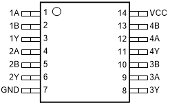
The SN74HCT08N comes in a 14-pin Dual In-line Package (DIP). The pinout and descriptions are as follows:
| Pin Number | Pin Name | Description |
|---|---|---|
| 1 | 1A | Input A for Gate 1 |
| 2 | 1B | Input B for Gate 1 |
| 3 | 1Y | Output Y for Gate 1 |
| 4 | 2A | Input A for Gate 2 |
| 5 | 2B | Input B for Gate 2 |
| 6 | 2Y | Output Y for Gate 2 |
| 7 | GND | Ground |
| 8 | 3Y | Output Y for Gate 3 |
| 9 | 3A | Input A for Gate 3 |
| 10 | 3B | Input B for Gate 3 |
| 11 | 4Y | Output Y for Gate 4 |
| 12 | 4A | Input A for Gate 4 |
| 13 | 4B | Input B for Gate 4 |
| 14 | Vcc | Positive Supply Voltage |
Usage Instructions
How to Use the SN74HCT08N in a Circuit
- Power Supply: Connect the Vcc pin (Pin 14) to a 5V power supply and the GND pin (Pin 7) to ground.
- Inputs: Provide the input signals to the respective input pins (e.g., 1A and 1B for Gate 1).
- Outputs: The logical AND result of the inputs will be available at the corresponding output pin (e.g., 1Y for Gate 1).
- Load Considerations: Ensure the output current does not exceed the maximum rating of ±25mA to avoid damage.
Important Considerations and Best Practices
- Use decoupling capacitors (e.g., 0.1µF) near the Vcc pin to stabilize the power supply and reduce noise.
- Ensure input voltages are within the specified range (0V to 5.5V) to prevent malfunction or damage.
- Avoid leaving input pins floating; connect unused inputs to GND or Vcc to ensure proper operation.
Example: Connecting SN74HCT08N to an Arduino UNO
The SN74HCT08N can be easily interfaced with an Arduino UNO for digital logic operations. Below is an example of how to use the component to perform an AND operation on two digital signals.
Circuit Connections
- Connect Pin 14 (Vcc) to the Arduino's 5V pin.
- Connect Pin 7 (GND) to the Arduino's GND pin.
- Connect two digital output pins of the Arduino (e.g., D2 and D3) to 1A (Pin 1) and 1B (Pin 2), respectively.
- Connect the output pin 1Y (Pin 3) to another digital input pin of the Arduino (e.g., D4).
Arduino Code
// Define input and output pins
const int inputA = 2; // Arduino pin connected to 1A
const int inputB = 3; // Arduino pin connected to 1B
const int outputY = 4; // Arduino pin connected to 1Y

void setup() {
  // Set input pins as outputs to drive the SN74HCT08N
  pinMode(inputA, OUTPUT);
  pinMode(inputB, OUTPUT);

  // Set output pin as input to read the AND gate result
  pinMode(outputY, INPUT);

  // Initialize serial communication for debugging
  Serial.begin(9600);
}

void loop() {
  // Example: Test the AND gate with different input combinations
  for (int a = 0; a <= 1; a++) {
    for (int b = 0; b <= 1; b++) {
      digitalWrite(inputA, a); // Set input A
      digitalWrite(inputB, b); // Set input B

      delay(10); // Small delay for signal stabilization

      int result = digitalRead(outputY); // Read the AND gate output

      // Print the inputs and output to the Serial Monitor
      Serial.print("Input A: ");
      Serial.print(a);
      Serial.print(", Input B: ");
      Serial.print(b);
      Serial.print(", Output Y: ");
      Serial.println(result);

      delay(1000); // Wait before the next test
    }
  }
}
Troubleshooting and FAQs
Common Issues and Solutions
No Output Signal:
- Ensure the power supply is properly connected to the Vcc and GND pins.
- Verify that the input signals are within the specified voltage range.
Incorrect Output:
- Check for floating input pins; connect unused inputs to GND or Vcc.
- Verify the connections and ensure the input signals are stable.
Overheating:
- Ensure the output current does not exceed the maximum rating of ±25mA.
- Check for short circuits or excessive load on the output pins.
FAQs
Q1: Can the SN74HCT08N operate at 3.3V?
A1: No, the SN74HCT08N requires a supply voltage between 4.5V and 5.5V. For 3.3V operation, consider using a different logic family, such as the 74LVC series.
Q2: What happens if I leave an input pin unconnected?
A2: Floating input pins can cause unpredictable behavior. Always connect unused inputs to GND or Vcc.
Q3: Can I use the SN74HCT08N for high-speed applications?
A3: Yes, the SN74HCT08N has a typical propagation delay of 14ns, making it suitable for many high-speed digital applications.