Cirkit Designer Logo
Cirkit Designer
Your all-in-one circuit design IDE
Home / 
Component Documentation

How to Use Optacoupler: Examples, Pinouts, and Specs

Image of Optacoupler
Cirkit Designer LogoDesign with Optacoupler in Cirkit Designer

Introduction

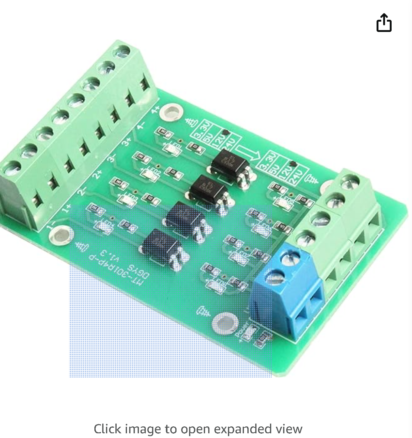
An optocoupler, also known as an optoisolator, is an electronic component that transfers electrical signals between two isolated circuits by using light. The Noyito MT-301R4P-P YSZK V1.4 is a specific model of optocoupler that provides electrical isolation and noise reduction, which is crucial in many applications where signal integrity and isolation from high voltages are required. Common applications include microcontroller input/output switching, signal isolation in power electronics, and interfacing between different voltage levels in a system.

Explore Projects Built with Optacoupler

Use Cirkit Designer to design, explore, and prototype these projects online. Some projects support real-time simulation. Click "Open Project" to start designing instantly!
Arduino Nano Controlled Octocoupler Interface for Signal Isolation
Image of complete togba no lcd: A project utilizing Optacoupler in a practical application
This circuit uses optocouplers paired with 220-ohm resistors to interface an Arduino Nano with an external device via a 5-pin relimate connector, providing electrical isolation and signal transfer while protecting the microcontroller. The Arduino's digital I/O pins are connected to the optocouplers, but the control logic is not yet defined in the provided code.
Cirkit Designer LogoOpen Project in Cirkit Designer
Wi-Fi Controlled Octocoupler Circuit with Wemos D1 Mini
Image of Opto: A project utilizing Optacoupler in a practical application
This circuit uses a Wemos D1 Mini microcontroller to control an optocoupler, which in turn interfaces with an external system. The microcontroller drives the optocoupler through a 220-ohm resistor, allowing for electrical isolation between the microcontroller and the external connections.
Cirkit Designer LogoOpen Project in Cirkit Designer
Arduino UNO-Based Optocoupler Control Circuit with Pushbutton Interface
Image of DVM1a: A project utilizing Optacoupler in a practical application
This circuit involves an Arduino UNO controlling two 4N35 optocouplers, which are used to isolate different sections of the circuit. The circuit also includes a pushbutton for user input, resistors for current limiting, and a ceramic capacitor for noise filtering.
Cirkit Designer LogoOpen Project in Cirkit Designer
Cellular-Connected ESP32-CAM with Real-Time Clock and Isolated Control
Image of LRCM PHASE 2 PRO: A project utilizing Optacoupler in a practical application
This circuit integrates a LilyGo-SIM7000G module with an RTC DS3231 for timekeeping, interfaced via I2C (SCL and SDA lines). An 8-Channel OPTO-COUPLER is used to isolate and interface external signals with the LilyGo-SIM7000G's GPIOs. Power is managed by a Buck converter, which steps down voltage from a DC Power Source to supply the ESP32-CAM and LilyGo-SIM7000G modules, as well as the OPTO-COUPLER.
Cirkit Designer LogoOpen Project in Cirkit Designer

Explore Projects Built with Optacoupler

Use Cirkit Designer to design, explore, and prototype these projects online. Some projects support real-time simulation. Click "Open Project" to start designing instantly!
Image of complete togba no lcd: A project utilizing Optacoupler in a practical application
Arduino Nano Controlled Octocoupler Interface for Signal Isolation
This circuit uses optocouplers paired with 220-ohm resistors to interface an Arduino Nano with an external device via a 5-pin relimate connector, providing electrical isolation and signal transfer while protecting the microcontroller. The Arduino's digital I/O pins are connected to the optocouplers, but the control logic is not yet defined in the provided code.
Cirkit Designer LogoOpen Project in Cirkit Designer
Image of Opto: A project utilizing Optacoupler in a practical application
Wi-Fi Controlled Octocoupler Circuit with Wemos D1 Mini
This circuit uses a Wemos D1 Mini microcontroller to control an optocoupler, which in turn interfaces with an external system. The microcontroller drives the optocoupler through a 220-ohm resistor, allowing for electrical isolation between the microcontroller and the external connections.
Cirkit Designer LogoOpen Project in Cirkit Designer
Image of DVM1a: A project utilizing Optacoupler in a practical application
Arduino UNO-Based Optocoupler Control Circuit with Pushbutton Interface
This circuit involves an Arduino UNO controlling two 4N35 optocouplers, which are used to isolate different sections of the circuit. The circuit also includes a pushbutton for user input, resistors for current limiting, and a ceramic capacitor for noise filtering.
Cirkit Designer LogoOpen Project in Cirkit Designer
Image of LRCM PHASE 2 PRO: A project utilizing Optacoupler in a practical application
Cellular-Connected ESP32-CAM with Real-Time Clock and Isolated Control
This circuit integrates a LilyGo-SIM7000G module with an RTC DS3231 for timekeeping, interfaced via I2C (SCL and SDA lines). An 8-Channel OPTO-COUPLER is used to isolate and interface external signals with the LilyGo-SIM7000G's GPIOs. Power is managed by a Buck converter, which steps down voltage from a DC Power Source to supply the ESP32-CAM and LilyGo-SIM7000G modules, as well as the OPTO-COUPLER.
Cirkit Designer LogoOpen Project in Cirkit Designer

Technical Specifications

Key Technical Details

  • Forward Voltage (LED): 1.2V typical
  • Forward Current (LED): 10mA to 20mA
  • Collector-Emitter Voltage (Transistor): 70V maximum
  • Collector Current (Transistor): 50mA maximum
  • Isolation Voltage: 5000Vrms minimum
  • Current Transfer Ratio (CTR): 50% to 600% at IF=5mA, VCE=5V
  • Response Time: 5µs typical

Pin Configuration and Descriptions

Pin Number Name Description
1 Anode (A) Anode of the internal LED. Connect to positive voltage.
2 Cathode (K) Cathode of the internal LED. Connect to ground.
3 Collector (C) Collector of the phototransistor. Connect to the output circuit.
4 Emitter (E) Emitter of the phototransistor. Connect to ground of the output circuit.

Usage Instructions

How to Use the Optocoupler in a Circuit

  1. Input Side (LED):

    • Connect the anode to the positive voltage through a current-limiting resistor.
    • Connect the cathode to the ground of the input circuit.
  2. Output Side (Phototransistor):

    • Connect the collector to the positive voltage of the output circuit.
    • Connect the emitter to the ground of the output circuit.
    • Place a pull-up resistor between the collector and the positive voltage if needed.

Important Considerations and Best Practices

  • Always use a current-limiting resistor on the input side to prevent damage to the LED.
  • Ensure that the voltage and current ratings are not exceeded on both the input and output sides.
  • Consider the CTR and ensure that the output current is sufficient for the load.
  • Keep the response time in mind for high-speed applications.

Troubleshooting and FAQs

Common Issues

  • LED Not Lighting Up:

    • Check the polarity of the LED pins.
    • Ensure the current-limiting resistor value is correct.
    • Verify that the input voltage is within the specified range.
  • No Output Signal:

    • Confirm that the phototransistor is correctly connected.
    • Check if the LED is operational and emitting light.
    • Ensure the load on the output side is within the specified current limit.

Solutions and Tips

  • If the LED is not lighting up, measure the voltage across the LED pins to ensure it falls within the forward voltage range.
  • For no output signal, measure the voltage at the collector to check if the phototransistor is conducting.
  • Use an oscilloscope to verify the signal integrity and response time.

FAQs

Q: Can I use this optocoupler for high-speed applications? A: The response time of this optocoupler is 5µs, which may not be suitable for very high-speed applications. Consider the response time in your design.

Q: What is the purpose of the current-limiting resistor? A: The current-limiting resistor protects the LED from excessive current, which could lead to damage or reduced lifespan.

Q: How do I choose the value of the pull-up resistor on the output side? A: The pull-up resistor value depends on the voltage level of the output circuit and the desired current through the phototransistor. Use Ohm's law to calculate the appropriate value.

Example Code for Arduino UNO

// Example code to use an optocoupler with an Arduino UNO
const int ledPin = 13; // LED connected to digital pin 13
const int optoPin = 2; // Optocoupler input connected to digital pin 2

void setup() {
  pinMode(ledPin, OUTPUT); // Set the LED pin as output
  pinMode(optoPin, INPUT); // Set the optocoupler pin as input
}

void loop() {
  digitalWrite(ledPin, HIGH); // Turn on the LED
  delay(1000); // Wait for 1 second
  digitalWrite(ledPin, LOW); // Turn off the LED
  delay(1000); // Wait for 1 second

  // Read the state of the optocoupler
  int optoState = digitalRead(optoPin);
  // Print the state to the serial monitor
  Serial.println(optoState);
}

Remember to limit the current through the LED on the input side of the optocoupler by using an appropriate resistor. The value of the resistor can be calculated using Ohm's law: R = (Vsource - Vf) / If, where Vf is the forward voltage of the LED and If is the desired forward current.