How to Use 2 channel 12 V relay module: Examples, Pinouts, and Specs
Introduction
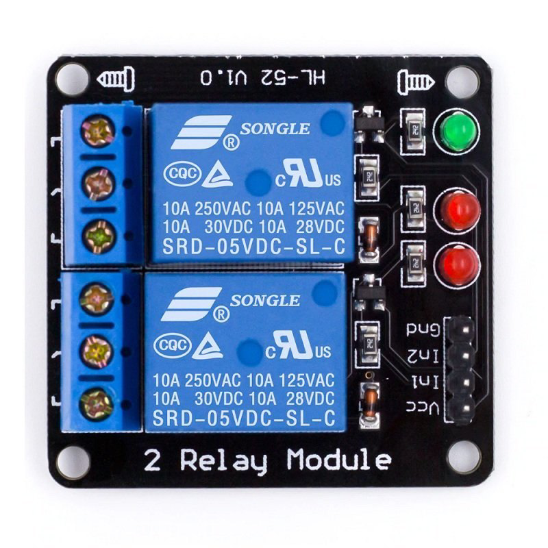
The 2 Channel 12V Relay Module is a versatile electronic component designed to control high-power devices using low-power signals. Each relay on the module can switch devices on and off with a 12V signal, making it ideal for applications where you need to control high-voltage or high-current devices such as lights, motors, and other electrical appliances. This module is commonly used in home automation, industrial automation, and various DIY projects.
Explore Projects Built with 2 channel 12 V relay module

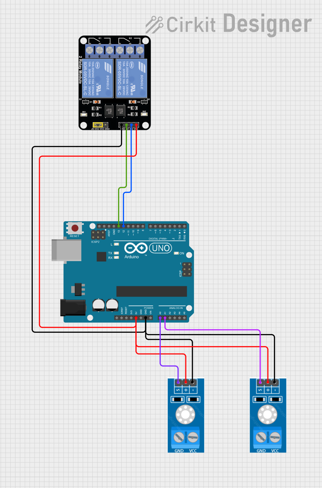

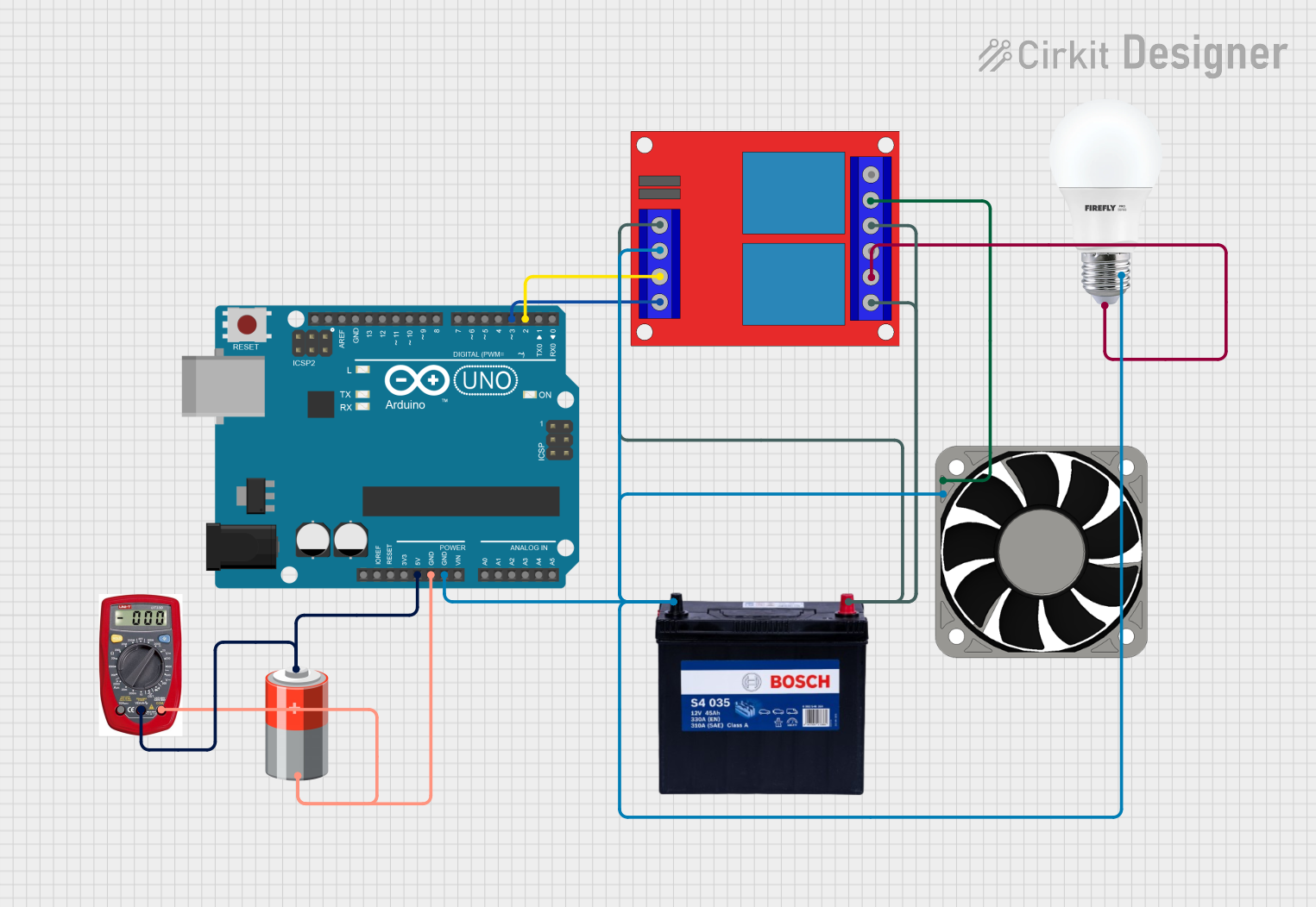
Explore Projects Built with 2 channel 12 V relay module
Technical Specifications
Key Technical Details
| Parameter | Value |
|---|---|
| Operating Voltage | 12V DC |
| Trigger Voltage | 5V DC |
| Current Consumption | 15-20mA per relay |
| Relay Type | SPDT (Single Pole Double Throw) |
| Max Switching Voltage | 250V AC / 30V DC |
| Max Switching Current | 10A |
| Dimensions | 50mm x 40mm x 20mm |
Pin Configuration and Descriptions
Relay Module Pinout
| Pin Name | Description |
|---|---|
| VCC | Connect to 12V DC power supply |
| GND | Ground |
| IN1 | Control signal for Relay 1 (active low) |
| IN2 | Control signal for Relay 2 (active low) |
| COM1 | Common terminal for Relay 1 |
| NO1 | Normally Open terminal for Relay 1 |
| NC1 | Normally Closed terminal for Relay 1 |
| COM2 | Common terminal for Relay 2 |
| NO2 | Normally Open terminal for Relay 2 |
| NC2 | Normally Closed terminal for Relay 2 |
Usage Instructions
How to Use the Component in a Circuit
Power Supply:
- Connect the VCC pin to a 12V DC power supply.
- Connect the GND pin to the ground of the power supply.
Control Signals:
- Connect the IN1 pin to a digital output pin of your microcontroller (e.g., Arduino).
- Connect the IN2 pin to another digital output pin of your microcontroller.
Load Connections:
- Connect the device you want to control to the COM1 and NO1/NC1 terminals for Relay 1.
- Connect another device to the COM2 and NO2/NC2 terminals for Relay 2.
Important Considerations and Best Practices
- Ensure that the power supply voltage matches the operating voltage of the relay module (12V DC).
- Use appropriate flyback diodes across the relay coils to protect your microcontroller from voltage spikes.
- Avoid exceeding the maximum switching voltage and current ratings to prevent damage to the relays.
- Use proper insulation and safety measures when dealing with high-voltage AC loads.
Example Code for Arduino UNO
/*
 * Example code to control a 2 Channel 12V Relay Module using Arduino UNO.
 * This code will alternately switch the relays on and off every second.
 */

const int relay1Pin = 7; // Digital pin connected to IN1
const int relay2Pin = 8; // Digital pin connected to IN2

void setup() {
  // Initialize the relay control pins as outputs
  pinMode(relay1Pin, OUTPUT);
  pinMode(relay2Pin, OUTPUT);

  // Initially turn off both relays
  digitalWrite(relay1Pin, HIGH); // Relay is active low
  digitalWrite(relay2Pin, HIGH); // Relay is active low
}

void loop() {
  // Turn on Relay 1 and turn off Relay 2
  digitalWrite(relay1Pin, LOW);  // Activate Relay 1
  digitalWrite(relay2Pin, HIGH); // Deactivate Relay 2
  delay(1000); // Wait for 1 second

  // Turn off Relay 1 and turn on Relay 2
  digitalWrite(relay1Pin, HIGH); // Deactivate Relay 1
  digitalWrite(relay2Pin, LOW);  // Activate Relay 2
  delay(1000); // Wait for 1 second
}
Troubleshooting and FAQs
Common Issues Users Might Face
Relays Not Activating:
- Ensure that the VCC and GND pins are properly connected to a 12V DC power supply.
- Verify that the control signals (IN1 and IN2) are receiving the correct voltage levels from the microcontroller.
Microcontroller Resetting:
- This could be due to voltage spikes caused by the relay coils. Use flyback diodes across the relay coils to mitigate this issue.
Load Not Switching:
- Check the connections to the COM, NO, and NC terminals.
- Ensure that the load does not exceed the maximum switching voltage and current ratings of the relay.
Solutions and Tips for Troubleshooting
- Double-check Wiring: Ensure all connections are secure and correctly placed.
- Use Flyback Diodes: Place diodes across relay coils to protect the microcontroller from voltage spikes.
- Check Power Supply: Make sure the power supply provides a stable 12V DC output.
- Test Relays Individually: Isolate and test each relay to ensure they are functioning correctly.
By following this documentation, you should be able to effectively use the 2 Channel 12V Relay Module in your projects, ensuring reliable control of high-power devices with low-power signals.