How to Use MPU: Examples, Pinouts, and Specs
Introduction
A Microprocessor Unit (MPU) is the central processing unit (CPU) of a computer or embedded system. It is responsible for executing instructions, performing arithmetic and logic operations, and processing data. MPUs are the core of modern computing systems, enabling the execution of software programs and the control of hardware components.
Explore Projects Built with MPU

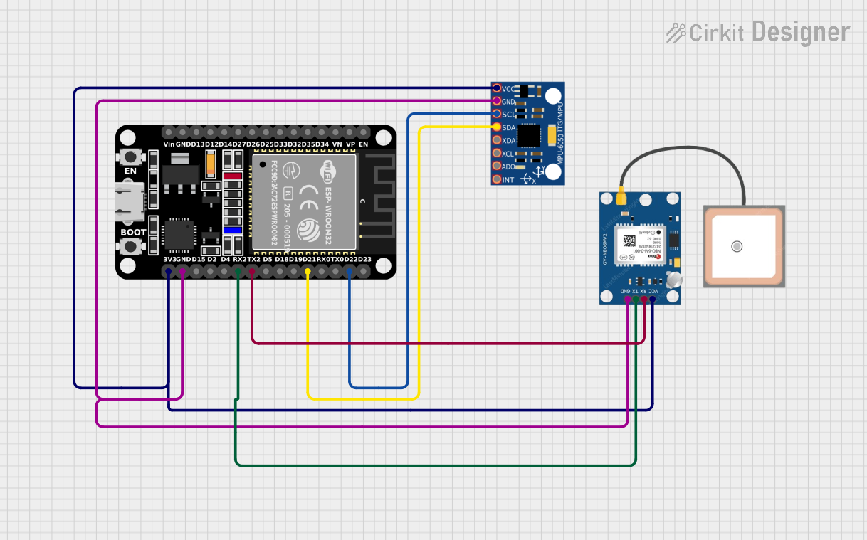
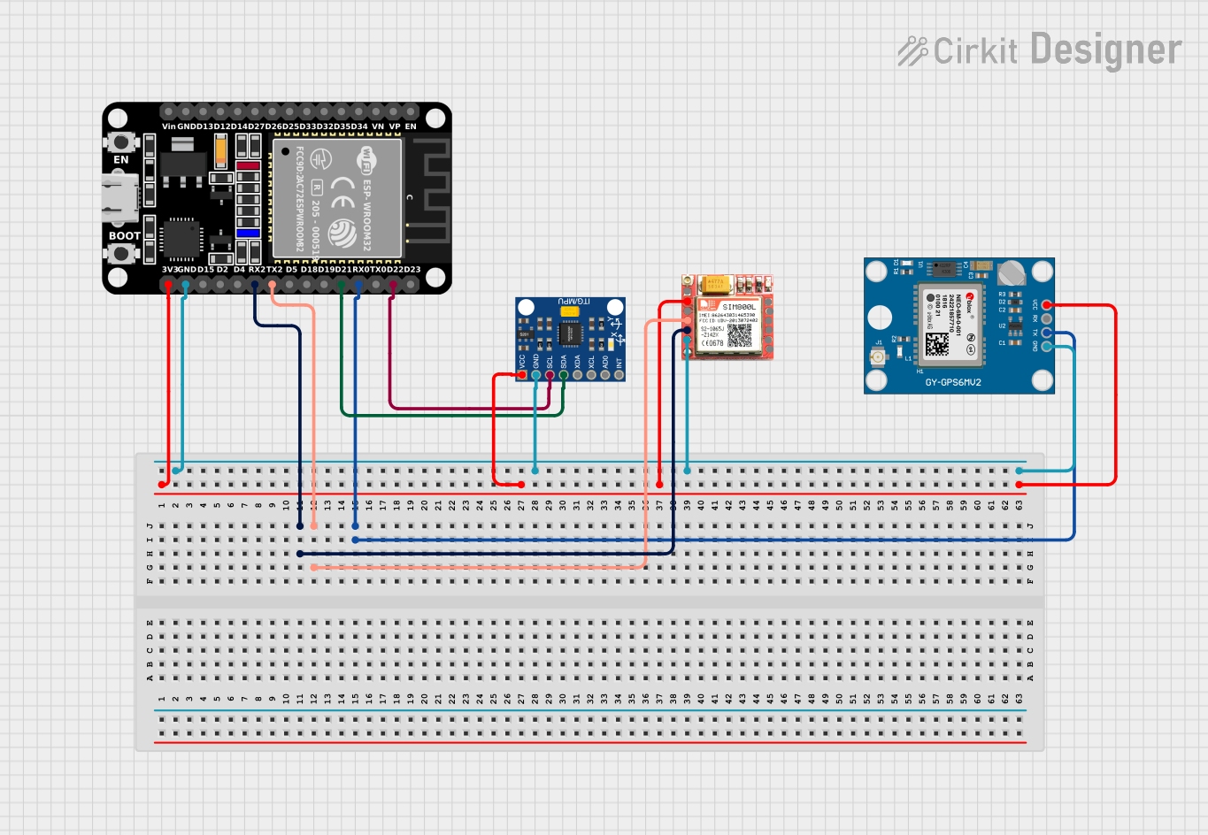
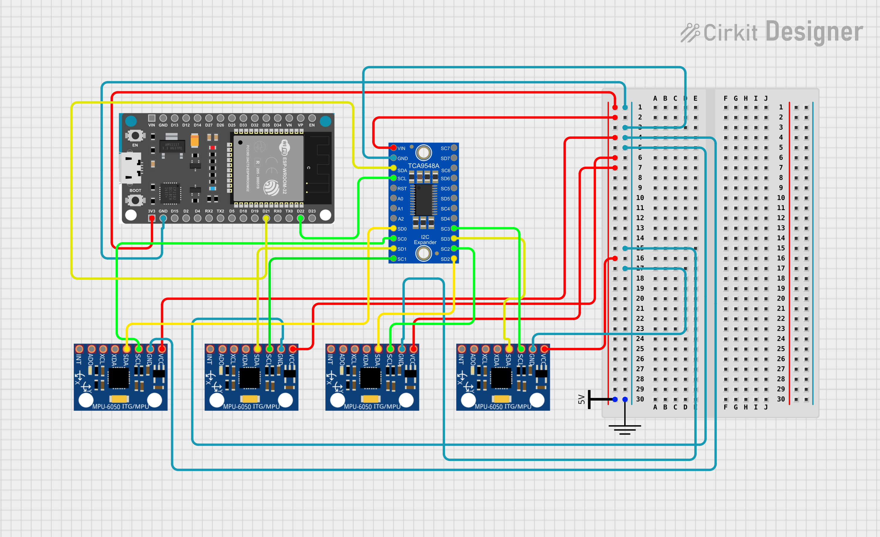
Explore Projects Built with MPU
Common Applications and Use Cases
- Embedded systems in consumer electronics (e.g., smartphones, smart appliances)
- Industrial automation and control systems
- Automotive systems (e.g., engine control units, infotainment systems)
- IoT (Internet of Things) devices
- Robotics and artificial intelligence applications
- General-purpose computing in personal computers and servers
Technical Specifications
The technical specifications of an MPU can vary widely depending on the model and manufacturer. Below are general specifications commonly associated with MPUs:
| Specification | Description |
|---|---|
| Clock Speed | Typically ranges from a few MHz to several GHz |
| Instruction Set | Varies by architecture (e.g., x86, ARM, RISC-V) |
| Data Bus Width | Commonly 8-bit, 16-bit, 32-bit, or 64-bit |
| Operating Voltage | Typically between 1.2V and 5V |
| Power Consumption | Varies based on clock speed and architecture; low-power MPUs consume <1W |
| Cache Memory | L1, L2, and sometimes L3 cache for faster data access |
| GPIO Pins | General-purpose input/output pins for interfacing with peripherals |
| Communication Interfaces | UART, SPI, I2C, CAN, USB, Ethernet, etc. |
| Package Type | DIP, QFP, BGA, or other surface-mount or through-hole packages |
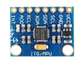
Pin Configuration and Descriptions
The pin configuration of an MPU depends on the specific model. Below is an example of a generic MPU pinout:
| Pin Name | Type | Description |
|---|---|---|
| VCC | Power | Power supply input |
| GND | Ground | Ground connection |
| CLK | Input | Clock signal input for timing and synchronization |
| RESET | Input | Resets the MPU to its initial state |
| GPIOx | Input/Output | General-purpose input/output pins for interfacing with peripherals |
| TX | Output | Transmit pin for UART communication |
| RX | Input | Receive pin for UART communication |
| SPI_MOSI | Output | Master Out Slave In pin for SPI communication |
| SPI_MISO | Input | Master In Slave Out pin for SPI communication |
| SPI_SCK | Input | Clock pin for SPI communication |
| I2C_SDA | Input/Output | Data line for I2C communication |
| I2C_SCL | Input | Clock line for I2C communication |
Refer to the datasheet of your specific MPU model for exact pin configurations.
Usage Instructions
How to Use the MPU in a Circuit
- Power Supply: Connect the VCC and GND pins to the appropriate power supply. Ensure the voltage matches the MPU's operating range.
- Clock Signal: Provide a stable clock signal to the CLK pin. Many MPUs require an external crystal oscillator.
- Reset: Connect the RESET pin to a push-button or circuit to allow manual or automatic resetting.
- Peripheral Connections: Use GPIO pins to interface with sensors, actuators, or other peripherals.
- Communication: Connect the appropriate communication pins (e.g., UART, SPI, I2C) to external devices for data exchange.
Important Considerations and Best Practices
- Voltage Levels: Ensure all connected devices operate at compatible voltage levels to avoid damage.
- Decoupling Capacitors: Place decoupling capacitors near the power pins to stabilize the power supply.
- Clock Stability: Use a high-quality crystal oscillator for accurate timing.
- Heat Management: For high-performance MPUs, consider adding a heat sink or fan to manage heat dissipation.
- Programming: Use a compatible programmer or development board to upload firmware to the MPU.
Example: Connecting an MPU to an Arduino UNO
Below is an example of how to interface an MPU with an Arduino UNO using I2C communication:
Circuit Connections
- Connect the MPU's
VCCto the Arduino's5Vpin. - Connect the MPU's
GNDto the Arduino'sGNDpin. - Connect the MPU's
I2C_SDAto the Arduino'sA4pin. - Connect the MPU's
I2C_SCLto the Arduino'sA5pin.
Arduino Code Example
#include <Wire.h> // Include the Wire library for I2C communication

#define MPU_ADDRESS 0x68 // Replace with your MPU's I2C address

void setup() {
  Wire.begin(); // Initialize I2C communication
  Serial.begin(9600); // Start serial communication for debugging

  // Wake up the MPU by writing to its power management register
  Wire.beginTransmission(MPU_ADDRESS);
  Wire.write(0x6B); // Power management register address
  Wire.write(0x00); // Set to 0 to wake up the MPU
  Wire.endTransmission();

  Serial.println("MPU initialized.");
}

void loop() {
  Wire.beginTransmission(MPU_ADDRESS);
  Wire.write(0x3B); // Starting register address for accelerometer data
  Wire.endTransmission(false);
  Wire.requestFrom(MPU_ADDRESS, 6, true); // Request 6 bytes of data

  int16_t accelX = (Wire.read() << 8) | Wire.read(); // Combine high and low bytes
  int16_t accelY = (Wire.read() << 8) | Wire.read();
  int16_t accelZ = (Wire.read() << 8) | Wire.read();

  Serial.print("Accel X: "); Serial.print(accelX);
  Serial.print(" | Accel Y: "); Serial.print(accelY);
  Serial.print(" | Accel Z: "); Serial.println(accelZ);

  delay(500); // Wait 500ms before the next reading
}
Troubleshooting and FAQs
Common Issues
MPU Not Responding
- Cause: Incorrect I2C address or wiring.
- Solution: Verify the I2C address and check all connections.
Inconsistent Data Readings
- Cause: Unstable power supply or noisy environment.
- Solution: Add decoupling capacitors and ensure a clean power source.
Overheating
- Cause: High clock speed or insufficient cooling.
- Solution: Reduce clock speed or add a heat sink.
Communication Errors
- Cause: Incorrect pull-up resistors on I2C lines.
- Solution: Add 4.7kΩ pull-up resistors to the SDA and SCL lines.
FAQs
Q: Can I use an MPU with a 3.3V system?
A: Yes, but ensure the MPU supports 3.3V operation or use a level shifter for compatibility.
Q: How do I find the I2C address of my MPU?
A: Use an I2C scanner sketch on your microcontroller to detect the address.
Q: What is the difference between an MPU and a microcontroller?
A: An MPU is a CPU that requires external memory and peripherals, while a microcontroller integrates these components into a single chip.