
How to Use HMC5843: Examples, Pinouts, and Specs
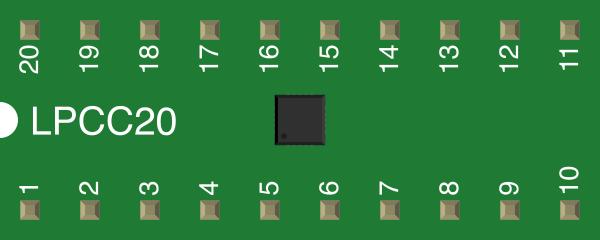
 Design with HMC5843 in Cirkit Designer
Introduction
The HMC5843 is a three-axis digital magnetometer designed to measure magnetic fields with high precision. It is widely used in applications such as navigation systems, robotics, and electronic compasses. The device provides digital output data via I2C or SPI interfaces, making it easy to integrate into a variety of microcontroller-based systems. Its compact size and low power consumption make it ideal for portable and embedded applications.
Explore Projects Built with HMC5843
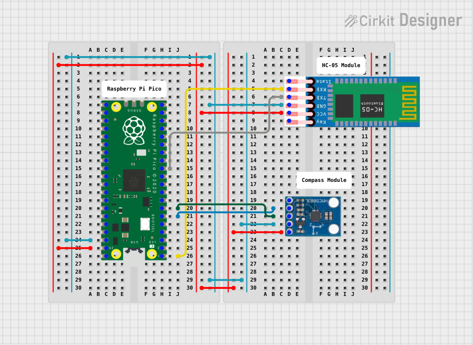 Open Project in Cirkit Designer
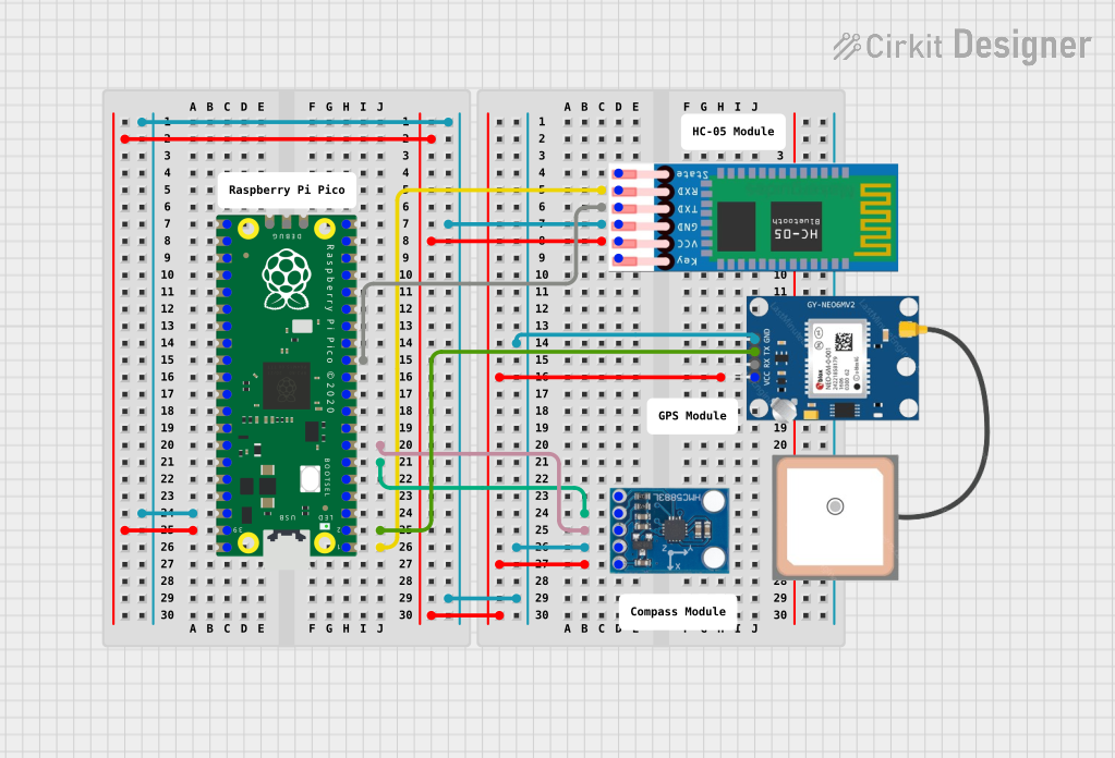 Open Project in Cirkit Designer
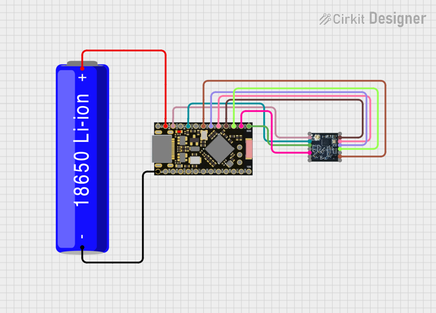 Open Project in Cirkit Designer
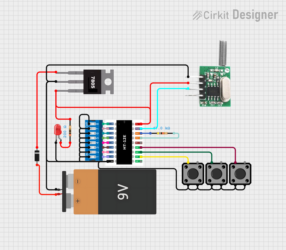 Open Project in Cirkit Designer
Explore Projects Built with HMC5843
Open Project in Cirkit DesignerOpen Project in Cirkit DesignerOpen Project in Cirkit DesignerOpen Project in Cirkit DesignerTechnical Specifications
The following table outlines the key technical details of the HMC5843:
| Parameter | Value |
|---|---|
| Operating Voltage | 2.5V to 3.3V |
| Interface | I2C (400 kHz) / SPI |
| Measurement Range | ±4 gauss |
| Resolution | 12-bit |
| Output Data Rate (ODR) | 0.5 Hz to 160 Hz |
| Operating Temperature | -40°C to +85°C |
| Power Consumption | 100 µA (typical) |
| Package | 16-pin LCC |
Pin Configuration and Descriptions
The HMC5843 is available in a 16-pin LCC package. The pin configuration and descriptions are as follows:
| Pin Number | Pin Name | Description |
|---|---|---|
| 1 | VDD | Power supply (2.5V to 3.3V) |
| 2 | GND | Ground |
| 3 | SCL | I2C clock input |
| 4 | SDA | I2C data input/output |
| 5 | DRDY | Data ready output (active high) |
| 6 | CS | Chip select for SPI (active low) |
| 7 | MOSI | SPI master-out/slave-in data line |
| 8 | MISO | SPI master-in/slave-out data line |
| 9 | SCLK | SPI clock input |
| 10-16 | NC | Not connected |
Usage Instructions
How to Use the HMC5843 in a Circuit
- Power Supply: Connect the VDD pin to a 2.5V to 3.3V power source and the GND pin to ground.
- Interface Selection: Choose between I2C or SPI communication:
- For I2C, connect the SCL and SDA pins to the corresponding I2C lines of your microcontroller.
- For SPI, connect the CS, MOSI, MISO, and SCLK pins to the respective SPI lines.
- Pull-Up Resistors: If using I2C, ensure pull-up resistors (typically 4.7 kΩ) are connected to the SCL and SDA lines.
- Data Ready Pin: Optionally, connect the DRDY pin to an interrupt-capable pin on your microcontroller to detect when new data is available.
- Bypass Capacitor: Place a 0.1 µF ceramic capacitor close to the VDD pin for power supply decoupling.
Arduino UNO Example Code
Below is an example of how to interface the HMC5843 with an Arduino UNO using the I2C protocol:
#include <Wire.h> // Include the Wire library for I2C communication

#define HMC5843_ADDRESS 0x1E // I2C address of the HMC5843

void setup() {
  Wire.begin(); // Initialize I2C communication
  Serial.begin(9600); // Start serial communication for debugging

  // Configure the HMC5843
  Wire.beginTransmission(HMC5843_ADDRESS);
  Wire.write(0x00); // Select configuration register A
  Wire.write(0x70); // Set measurement mode to normal and data rate to 15 Hz
  Wire.endTransmission();

  Wire.beginTransmission(HMC5843_ADDRESS);
  Wire.write(0x01); // Select configuration register B
  Wire.write(0xA0); // Set gain to ±1.3 Gauss
  Wire.endTransmission();

  Wire.beginTransmission(HMC5843_ADDRESS);
  Wire.write(0x02); // Select mode register
  Wire.write(0x00); // Set continuous measurement mode
  Wire.endTransmission();
}

void loop() {
  int16_t x, y, z;

  // Request 6 bytes of data from the HMC5843
  Wire.beginTransmission(HMC5843_ADDRESS);
  Wire.write(0x03); // Set pointer to data output X MSB register
  Wire.endTransmission();
  Wire.requestFrom(HMC5843_ADDRESS, 6);

  if (Wire.available() == 6) {
    x = (Wire.read() << 8) | Wire.read(); // Combine MSB and LSB for X-axis
    z = (Wire.read() << 8) | Wire.read(); // Combine MSB and LSB for Z-axis
    y = (Wire.read() << 8) | Wire.read(); // Combine MSB and LSB for Y-axis
  }

  // Print the magnetic field values
  Serial.print("X: ");
  Serial.print(x);
  Serial.print(" Y: ");
  Serial.print(y);
  Serial.print(" Z: ");
  Serial.println(z);

  delay(100); // Delay for 100 ms
}
Important Considerations and Best Practices
- Magnetic Interference: Avoid placing the HMC5843 near ferromagnetic materials or strong magnetic fields, as these can affect accuracy.
- Calibration: Perform a calibration routine to account for hard and soft iron distortions in your environment.
- Power Supply Stability: Use a stable power supply to ensure consistent performance.
- Data Rate: Choose an appropriate output data rate (ODR) based on your application's requirements.
Troubleshooting and FAQs
Common Issues and Solutions
No Data Output:
- Ensure the HMC5843 is powered correctly (2.5V to 3.3V).
- Verify the I2C or SPI connections and check for loose wires.
- Confirm that the correct I2C address (0x1E) is being used.
Inaccurate Measurements:
- Perform a calibration routine to correct for environmental distortions.
- Check for nearby magnetic interference and relocate the sensor if necessary.
Communication Errors:
- Ensure pull-up resistors are present on the I2C lines.
- Verify that the SPI clock polarity and phase settings match the HMC5843's requirements.
FAQs
Q: Can the HMC5843 operate at 5V?
A: No, the HMC5843 operates within a voltage range of 2.5V to 3.3V. Using 5V may damage the device.
Q: How do I switch between I2C and SPI modes?
A: The HMC5843 automatically detects the communication protocol based on the connections. Ensure only one protocol is connected at a time.
Q: What is the maximum measurement range of the HMC5843?
A: The HMC5843 can measure magnetic fields within a range of ±4 gauss.
Q: Do I need to calibrate the sensor?
A: Yes, calibration is recommended to achieve accurate measurements, especially in environments with magnetic distortions.