How to Use HUB12: Examples, Pinouts, and Specs
Introduction
HUB12 is a type of integrated circuit (IC) designed for connecting multiple devices within a network. It facilitates efficient data transfer and communication between connected devices, making it an essential component in applications requiring synchronized data exchange. HUB12 is commonly used in LED display systems, industrial automation, and other digital communication systems where multiple devices need to operate in unison.
Explore Projects Built with HUB12


Explore Projects Built with HUB12
Common Applications and Use Cases
- LED matrix displays and digital signage
- Industrial control systems
- Data communication networks
- Multi-device synchronization in embedded systems
Technical Specifications
Below are the key technical details and pin configuration for the HUB12 IC:
Key Technical Details
- Operating Voltage: 3.3V to 5V
- Maximum Current: 500mA
- Communication Protocol: Parallel data transfer
- Data Rate: Up to 25 MHz
- Operating Temperature: -40°C to 85°C
- Package Type: DIP (Dual In-line Package) or SMD (Surface Mount Device)
Pin Configuration and Descriptions
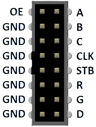
The HUB12 IC typically has a 16-pin configuration. Below is the pinout and description:
| Pin Number | Pin Name | Description |
|---|---|---|
| 1 | GND | Ground connection for the IC |
| 2 | VCC | Power supply input (3.3V to 5V) |
| 3 | DATA_IN | Input for serial data |
| 4 | CLK | Clock signal input |
| 5 | LATCH | Latch signal input to store data |
| 6 | OE | Output enable control |
| 7 | DATA_OUT | Output for serial data |
| 8 | A | Row address input (bit 0) |
| 9 | B | Row address input (bit 1) |
| 10 | C | Row address input (bit 2) |
| 11 | D | Row address input (bit 3) |
| 12 | E | Row address input (bit 4) |
| 13 | R1 | Red channel data for the first row |
| 14 | G1 | Green channel data for the first row |
| 15 | R2 | Red channel data for the second row |
| 16 | G2 | Green channel data for the second row |
Usage Instructions
How to Use the HUB12 in a Circuit
- Power Supply: Connect the VCC pin to a 3.3V or 5V power source and the GND pin to ground.
- Data Input: Feed serial data into the DATA_IN pin. Ensure the data format matches the IC's requirements.
- Clock Signal: Provide a clock signal to the CLK pin to synchronize data transfer.
- Latch Signal: Use the LATCH pin to store the incoming data into the internal registers.
- Output Enable: Control the OE pin to enable or disable the output.
- Row Addressing: Use the A, B, C, D, and E pins to select the desired row for data output.
- Data Output: The processed data will be available on the DATA_OUT pin for further use.
Important Considerations and Best Practices
- Use decoupling capacitors (e.g., 0.1µF) near the VCC pin to stabilize the power supply.
- Ensure the clock signal is clean and free of noise to avoid data corruption.
- Avoid exceeding the maximum voltage and current ratings to prevent damage to the IC.
- Use proper heat dissipation techniques if the IC operates at high frequencies or currents.
Example: Connecting HUB12 to an Arduino UNO
Below is an example of how to connect and control the HUB12 IC using an Arduino UNO:
// Example code to control HUB12 with Arduino UNO
// Ensure proper connections between Arduino and HUB12 pins

#define DATA_IN 2  // Arduino pin connected to HUB12 DATA_IN
#define CLK 3      // Arduino pin connected to HUB12 CLK
#define LATCH 4    // Arduino pin connected to HUB12 LATCH
#define OE 5       // Arduino pin connected to HUB12 OE

void setup() {
  pinMode(DATA_IN, OUTPUT);
  pinMode(CLK, OUTPUT);
  pinMode(LATCH, OUTPUT);
  pinMode(OE, OUTPUT);

  digitalWrite(OE, LOW);  // Enable output
}

void loop() {
  digitalWrite(LATCH, LOW);  // Prepare to send data

  for (int i = 0; i < 8; i++) {
    // Send 8 bits of data (example: alternating 1s and 0s)
    digitalWrite(DATA_IN, i % 2);
    digitalWrite(CLK, HIGH);  // Pulse the clock
    delayMicroseconds(10);    // Short delay for stability
    digitalWrite(CLK, LOW);
  }

  digitalWrite(LATCH, HIGH);  // Latch the data
  delay(1000);                // Wait for 1 second
}
Troubleshooting and FAQs
Common Issues and Solutions
No Output on Connected Devices
- Cause: Incorrect wiring or loose connections.
- Solution: Double-check all connections, especially power, ground, and data lines.
Flickering or Unstable Output
- Cause: Noisy clock signal or insufficient power supply.
- Solution: Use a clean clock signal and add decoupling capacitors near the IC.
Data Not Latching
- Cause: LATCH signal not being toggled correctly.
- Solution: Verify the LATCH pin is being pulsed high after sending data.
Overheating
- Cause: Exceeding current or voltage ratings.
- Solution: Ensure the IC operates within its specified limits and use proper heat dissipation.
FAQs
Q: Can HUB12 be used with 3.3V microcontrollers?
A: Yes, HUB12 is compatible with both 3.3V and 5V systems. Ensure the voltage levels match the microcontroller's output.
Q: What is the maximum data rate for HUB12?
A: The HUB12 supports data rates of up to 25 MHz, making it suitable for high-speed applications.
Q: How many devices can be connected using HUB12?
A: The number of devices depends on the specific application and the design of the network. HUB12 is commonly used in LED matrices with multiple rows and columns.
Q: Can HUB12 drive high-power LEDs directly?
A: No, HUB12 is not designed to drive high-power LEDs directly. Use external drivers or transistors for high-power applications.