How to Use Door lock: Examples, Pinouts, and Specs
Introduction
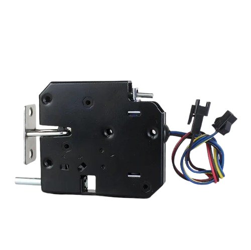
An electronic door lock is a device that operates by means of electric current to secure and manage access through a door. It can be controlled remotely, often integrated with systems to provide keyless entry, and can be connected to a network for access control. Common applications include residential homes, commercial buildings, and secure facilities where controlled access is necessary.
Explore Projects Built with Door lock
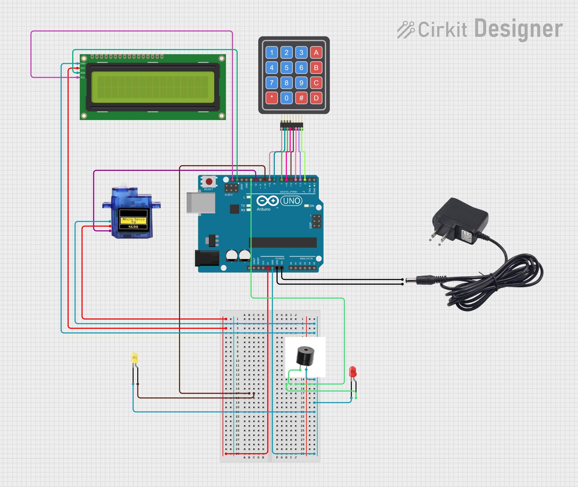
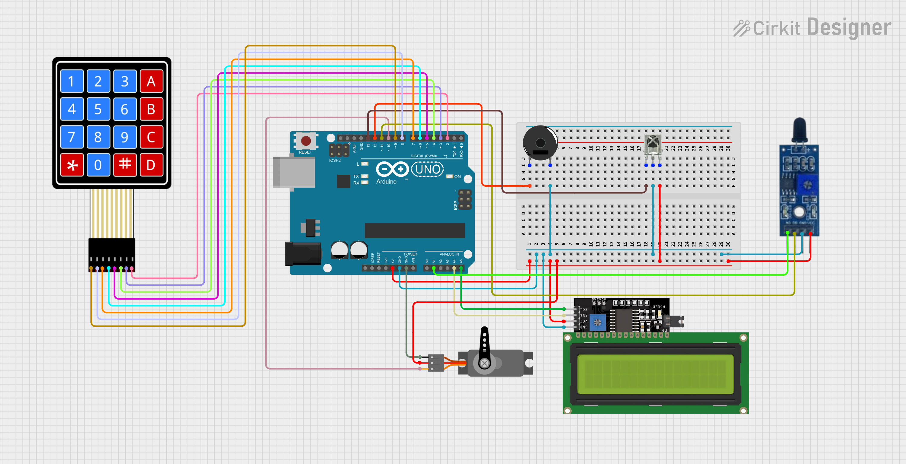
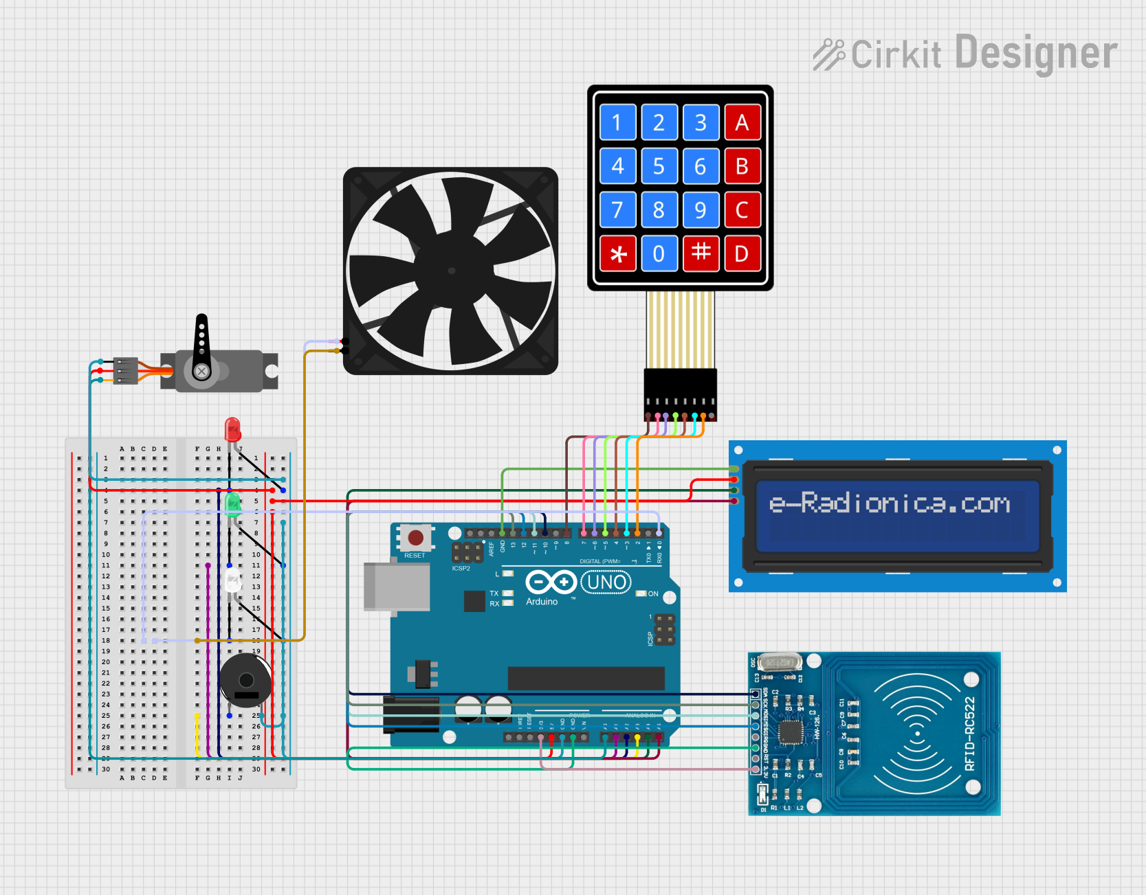
Explore Projects Built with Door lock
Technical Specifications
General Specifications
- Operating Voltage: Typically 12V DC
- Current Consumption: Varies with model (e.g., 100mA standby, 900mA actuation)
- Operating Temperature: -20°C to +60°C
- Humidity Tolerance: 0% to 95% non-condensing
Pin Configuration and Descriptions
| Pin Number | Description | Notes |
|---|---|---|
| 1 | Power Supply (Vcc) | Connect to 12V DC |
| 2 | Ground (GND) | Connect to system ground |
| 3 | Control Input | TTL compatible |
| 4 | Status Output | Open-collector, active low |
| 5 | Lock Mechanism | Connect to lock actuator |
Usage Instructions
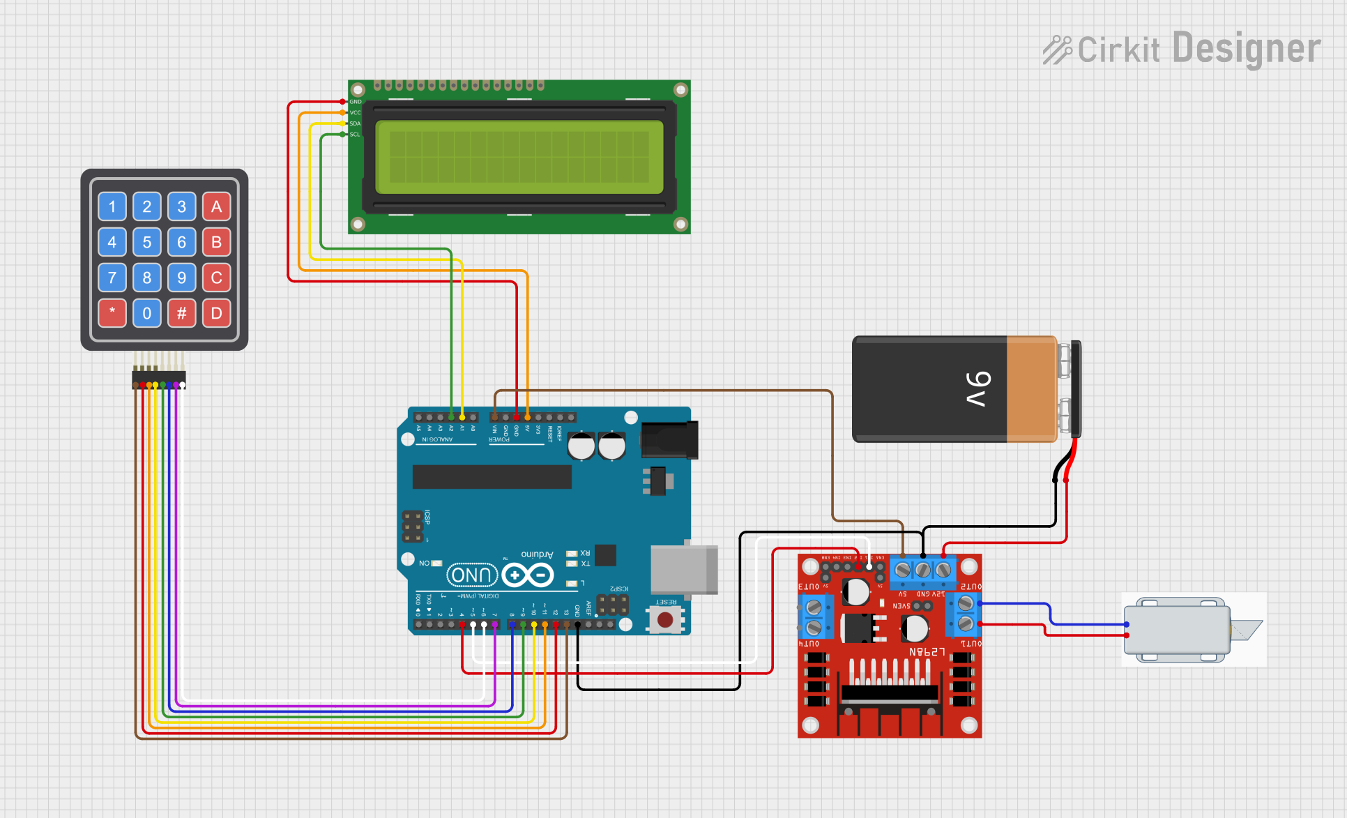
Integration with a Circuit
Power Supply: Ensure that the door lock is connected to a 12V DC power supply. The power supply should be capable of handling the current draw of the lock, especially during actuation.
Control Input: The control input can be connected to a microcontroller or other control systems. It is typically a TTL-level signal that, when driven high, will activate the lock mechanism.
Status Output: This output can be used to monitor the status of the lock. It is usually an open-collector output that requires a pull-up resistor to be read by a microcontroller.
Lock Mechanism: The mechanical part of the lock should be properly installed in the door, ensuring that the actuator has the correct range of motion and is securely fastened.
Best Practices
- Always use a diode across the lock actuator to prevent back EMF when the actuator is de-energized.
- Use a fuse or a current-limiting device to protect against overcurrent conditions.
- Ensure that all connections are secure and that wires are appropriately rated for the current draw of the lock.
- Test the lock mechanism manually before integrating it into an electronic system to ensure mechanical reliability.
Example Code for Arduino UNO
// Define the control pin for the door lock
const int lockControlPin = 3;

void setup() {
  // Set the control pin as an output
  pinMode(lockControlPin, OUTPUT);
  // Start with the lock in a secure state (locked)
  digitalWrite(lockControlPin, LOW);
}

void loop() {
  // Example code to unlock the door for 5 seconds
  unlockDoor();
  delay(5000); // Wait for 5 seconds
  lockDoor();
  delay(10000); // Wait for 10 seconds before the next unlock
}

// Function to unlock the door
void unlockDoor() {
  digitalWrite(lockControlPin, HIGH); // Apply voltage to control input
}

// Function to lock the door
void lockDoor() {
  digitalWrite(lockControlPin, LOW); // Remove voltage from control input
}
Troubleshooting and FAQs
Common Issues
- Lock does not actuate: Check the power supply and connections. Ensure the control input is receiving the correct signal.
- Intermittent operation: Inspect for loose connections or potential short circuits. Verify that the power supply can handle the current draw.
- Lock actuates unexpectedly: Ensure that there is no noise or unintended signals being sent to the control input.
FAQs
Q: Can the electronic door lock be powered by batteries? A: Yes, but ensure the batteries can provide sufficient current for the operation of the lock, especially during actuation.
Q: Is it possible to control the lock wirelessly? A: Yes, by integrating a wireless module (e.g., Wi-Fi, Bluetooth) with the control input, you can operate the lock remotely.
Q: What should I do if the lock is not responding to the control signal? A: Verify the control signal with an oscilloscope or logic analyzer. Check the voltage levels and signal integrity.
Remember, safety first! Always follow electrical codes and standards when installing and operating electronic door locks.