How to Use Microcontroller: Examples, Pinouts, and Specs
Introduction
The ESP32 is a powerful and versatile microcontroller developed by Espressif Systems. It is a compact integrated circuit designed to govern specific operations in embedded systems, featuring a dual-core processor, built-in Wi-Fi, Bluetooth capabilities, memory, and input/output peripherals. The ESP32 is widely used in IoT (Internet of Things) applications, home automation, wearable devices, and industrial automation due to its high performance, low power consumption, and extensive connectivity options.
Explore Projects Built with Microcontroller


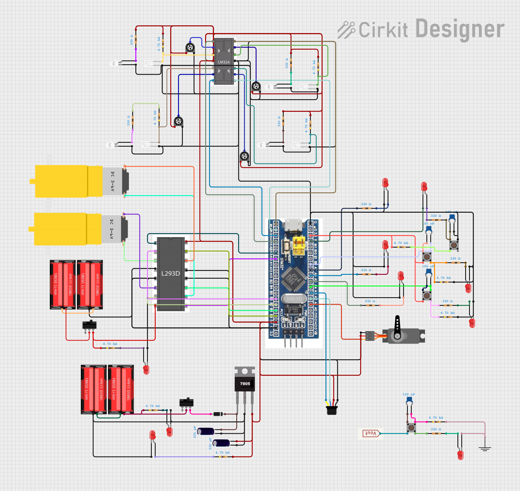
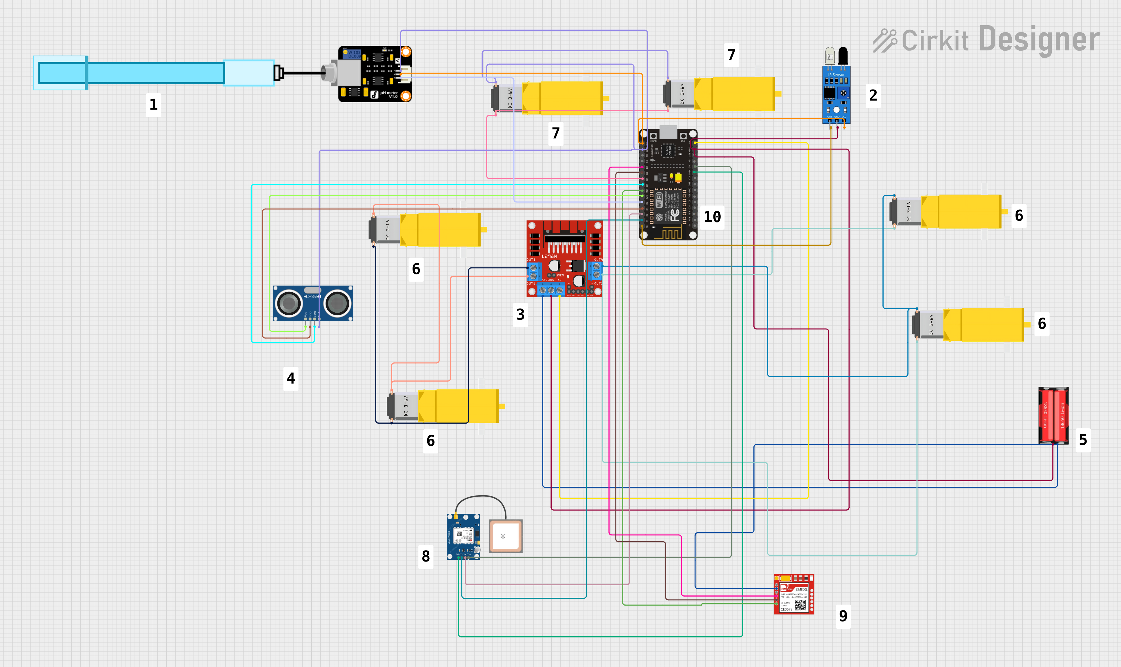
Explore Projects Built with Microcontroller
Common Applications and Use Cases
- IoT devices and smart home systems
- Wireless sensor networks
- Wearable technology
- Robotics and automation
- Data logging and monitoring systems
- Bluetooth-enabled devices
- Prototyping and educational projects
Technical Specifications
The ESP32 microcontroller offers a rich set of features and capabilities. Below are its key technical specifications:
Key Technical Details
- Processor: Dual-core Xtensa® 32-bit LX6 CPU
- Clock Speed: Up to 240 MHz
- Flash Memory: 4 MB (varies by module)
- SRAM: 520 KB
- Connectivity:
- Wi-Fi: 802.11 b/g/n
- Bluetooth: v4.2 BR/EDR and BLE
- Operating Voltage: 3.0V to 3.6V
- GPIO Pins: 34 (multipurpose)
- ADC Channels: 18 (12-bit resolution)
- DAC Channels: 2 (8-bit resolution)
- PWM Outputs: Up to 16 channels
- Communication Protocols: UART, SPI, I2C, I2S, CAN, Ethernet MAC
- Power Modes: Active, Light Sleep, Deep Sleep, Hibernation
- Operating Temperature: -40°C to +125°C
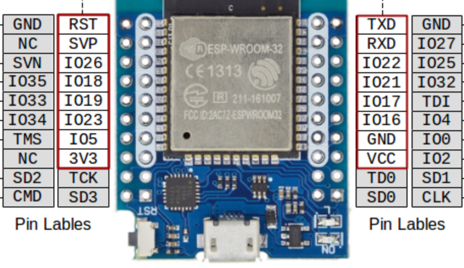
Pin Configuration and Descriptions
The ESP32 has a variety of pins for different functionalities. Below is a summary of the pin configuration:
| Pin Name | Function | Description |
|---|---|---|
| GPIO0 | General Purpose I/O, Boot | Used for boot mode selection and general I/O |
| GPIO1 (TXD0) | UART0 Transmit | Default UART0 TX pin |
| GPIO3 (RXD0) | UART0 Receive | Default UART0 RX pin |
| GPIO12-15 | General Purpose I/O, ADC, PWM | Can be used for analog input, PWM output, or general I/O |
| GPIO34-39 | Input Only | These pins are input-only and can be used for ADC or digital input |
| EN | Enable | Active-high enable pin; resets the chip when pulled low |
| VIN | Power Input | Main power input (5V) |
| GND | Ground | Ground connection |
| 3V3 | Power Output | Provides 3.3V output for external components |
Note: Not all GPIO pins support all functions simultaneously. Refer to the ESP32 datasheet for detailed pin multiplexing information.
Usage Instructions
The ESP32 microcontroller is highly versatile and can be used in a variety of circuits. Below are the steps and best practices for using the ESP32 in your projects.
How to Use the ESP32 in a Circuit
Powering the ESP32:
- Connect the VIN pin to a 5V power source or use the micro-USB port for power and programming.
- Ensure the GND pin is connected to the ground of your circuit.
Programming the ESP32:
- Use the Arduino IDE or Espressif's ESP-IDF (IoT Development Framework) for programming.
- Install the ESP32 board package in the Arduino IDE via the Board Manager.
- Connect the ESP32 to your computer using a USB cable.
Connecting Peripherals:
- Use GPIO pins for digital input/output.
- Connect sensors to ADC pins for analog input.
- Use UART, SPI, or I2C for communication with other devices.
Uploading Code:
- Select the correct board and port in the Arduino IDE.
- Write or load your code and click the "Upload" button.
Important Considerations and Best Practices
- Avoid exceeding the maximum voltage ratings for GPIO pins (3.3V).
- Use pull-up or pull-down resistors for input pins to prevent floating states.
- For power-sensitive applications, utilize the ESP32's sleep modes to conserve energy.
- Ensure proper decoupling capacitors are used near the power pins to reduce noise.
Example Code for Arduino IDE
Below is an example code to blink an LED connected to GPIO2:
// Define the LED pin
const int ledPin = 2; // GPIO2 is commonly used for onboard LEDs

void setup() {
  pinMode(ledPin, OUTPUT); // Set GPIO2 as an output pin
}

void loop() {
  digitalWrite(ledPin, HIGH); // Turn the LED on
  delay(1000);                // Wait for 1 second
  digitalWrite(ledPin, LOW);  // Turn the LED off
  delay(1000);                // Wait for 1 second
}
Tip: If the onboard LED does not blink, ensure the correct GPIO pin is specified in the code.
Troubleshooting and FAQs
Common Issues and Solutions
ESP32 Not Detected by Computer:
- Ensure the USB cable is functional and supports data transfer.
- Install the correct USB-to-serial driver for your operating system.
Code Upload Fails:
- Check the selected board and port in the Arduino IDE.
- Press and hold the "BOOT" button on the ESP32 while uploading the code.
Wi-Fi Connection Issues:
- Verify the SSID and password in your code.
- Ensure the Wi-Fi network is within range and supports 2.4 GHz (ESP32 does not support 5 GHz).
GPIO Pin Not Working:
- Confirm the pin is not being used for another function (e.g., boot mode).
- Check for proper wiring and connections.
FAQs
Q: Can the ESP32 operate on battery power?
A: Yes, the ESP32 can be powered by a battery. Use a 3.7V LiPo battery with a voltage regulator or a 5V power bank.
Q: How do I reset the ESP32?
A: Press the "EN" button on the board to reset the microcontroller.
Q: Can I use the ESP32 with 5V logic devices?
A: The ESP32 operates at 3.3V logic levels. Use a level shifter to interface with 5V devices.
Q: What is the maximum range of the ESP32's Wi-Fi?
A: The Wi-Fi range depends on the environment but typically extends up to 100 meters in open spaces.
By following this documentation, you can effectively utilize the ESP32 microcontroller in your projects and troubleshoot common issues.