How to Use SKR V1.4: Examples, Pinouts, and Specs
Introduction
The SKR V1.4, manufactured by BTT (BigTreeTech) with part ID 001, is a powerful 32-bit control board designed for 3D printers. It is based on the ARM Cortex-M3 processor, offering enhanced performance and flexibility compared to traditional 8-bit boards. The SKR V1.4 supports a wide range of stepper motor drivers, multiple connectivity options, and is compatible with popular open-source firmware like Marlin, making it a versatile choice for custom 3D printer builds and upgrades.
Explore Projects Built with SKR V1.4
Explore Projects Built with SKR V1.4
Common Applications and Use Cases
- Custom 3D printer builds
- Upgrading existing 3D printers for better performance
- CNC machines and laser engravers
- Robotics projects requiring precise motor control
Technical Specifications
Key Technical Details
- Processor: ARM Cortex-M3 (LPC1768, 32-bit)
- Input Voltage: 12V–24V DC
- Stepper Driver Support: Supports TMC, A4988, DRV8825, and other stepper drivers
- Connectivity:
- USB Type-B for firmware upload and communication
- SD card slot for offline printing
- UART, SPI, and I2C interfaces
- Firmware Compatibility: Marlin, Smoothieware
- Number of Stepper Motor Ports: 5 (X, Y, Z, E0, E1)
- Heated Bed Output: 1 channel
- Fan Outputs: 3 controllable fan ports
- Thermistor Inputs: 3 (for hotend, heated bed, and additional sensors)
- Expansion Ports: BLTouch, filament runout sensor, RGB LED, and more
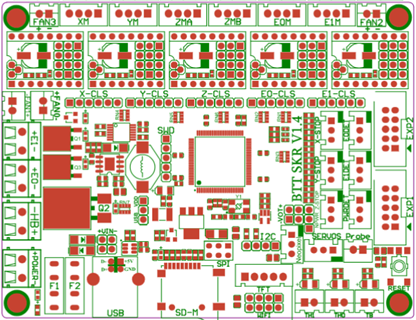
Pin Configuration and Descriptions
Main Connectors
| Pin Name | Description |
|---|---|
| X, Y, Z, E0, E1 | Stepper motor driver sockets for axis and extruder control |
| HE0, HE1 | Outputs for hotend heaters |
| BED | Output for heated bed |
| FAN0, FAN1, FAN2 | Controllable fan outputs |
| TH0, TH1, THB | Thermistor inputs for temperature monitoring |
| EXP1, EXP2 | Connectors for LCD or touchscreen displays |
| BLTouch | Dedicated port for auto bed leveling sensor |
| USB | USB Type-B port for firmware upload and PC communication |
| SD | SD card slot for offline printing |
Power Inputs
| Pin Name | Description |
|---|---|
| VIN | Main power input (12V–24V DC) |
| 5V | 5V power supply for logic circuits |
Communication Interfaces
| Pin Name | Description |
|---|---|
| UART | Serial communication interface |
| SPI | Serial Peripheral Interface |
| I2C | Inter-Integrated Circuit interface |
Usage Instructions
How to Use the SKR V1.4 in a Circuit
- Power Supply: Connect a 12V–24V DC power supply to the VIN and GND terminals. Ensure the power supply can handle the current requirements of your 3D printer.
- Stepper Drivers: Insert compatible stepper drivers (e.g., TMC2208, A4988) into the X, Y, Z, E0, and E1 sockets. Ensure the drivers are oriented correctly.
- Motors and Sensors: Connect stepper motors, thermistors, and endstops to their respective ports.
- Heaters and Fans: Attach the hotend heater, heated bed, and fans to the HE0, BED, and FAN ports.
- Firmware: Flash the board with compatible firmware (e.g., Marlin) using the USB port or SD card. Configure the firmware to match your hardware setup.
- LCD/Touchscreen: Connect an LCD or touchscreen display to the EXP1 and EXP2 ports if required.
- Additional Features: Attach optional components like a BLTouch sensor or filament runout sensor to their dedicated ports.
Important Considerations and Best Practices
- Stepper Driver Configuration: Set the correct microstepping and current limits on your stepper drivers before installation.
- Cooling: Ensure adequate cooling for the stepper drivers and the board to prevent overheating.
- Firmware Configuration: Customize the firmware (e.g., Marlin) to match your printer's hardware, including stepper motor steps/mm, thermistor types, and endstop logic.
- Wiring: Double-check all connections to avoid short circuits or incorrect wiring.
Example Code for Marlin Firmware Configuration
Below is an example of configuring the SKR V1.4 for use with an Arduino IDE-compatible Marlin firmware:
// Example Marlin configuration for SKR V1.4
// Ensure you select the correct board in the Marlin configuration file

#define MOTHERBOARD BOARD_BTT_SKR_V1_4
#define SERIAL_PORT -1  // Use USB for communication
#define SERIAL_PORT_2 0 // Optional second serial port

// Define stepper motor settings
#define DEFAULT_AXIS_STEPS_PER_UNIT   { 80, 80, 400, 500 } // X, Y, Z, E
#define DEFAULT_MAX_FEEDRATE          { 300, 300, 5, 25 }  // mm/s
#define DEFAULT_MAX_ACCELERATION      { 3000, 3000, 100, 1000 }

// Define thermistor types
#define TEMP_SENSOR_0 1  // Hotend thermistor
#define TEMP_SENSOR_BED 1 // Heated bed thermistor

// Enable BLTouch for auto bed leveling
#define BLTOUCH
#define AUTO_BED_LEVELING_BILINEAR
#define Z_SAFE_HOMING
Troubleshooting and FAQs
Common Issues and Solutions
Board Not Powering On:
- Ensure the power supply is connected correctly and providing the correct voltage (12V–24V).
- Check for loose or damaged wires.
Stepper Motors Not Moving:
- Verify the stepper drivers are installed correctly and configured for the correct current.
- Check the firmware configuration for motor settings.
Temperature Readings Incorrect:
- Ensure the thermistors are connected to the correct ports (TH0, TH1, THB).
- Verify the thermistor type is correctly defined in the firmware.
USB Connection Not Recognized:
- Install the correct USB drivers for the SKR V1.4.
- Try a different USB cable or port.
Firmware Not Flashing:
- Ensure the firmware file is named correctly (e.g.,
firmware.bin) and placed on the SD card. - Use a freshly formatted SD card (FAT32 format).
- Ensure the firmware file is named correctly (e.g.,
FAQs
Can I use the SKR V1.4 with TMC2209 drivers? Yes, the SKR V1.4 supports TMC2209 drivers. Ensure you configure the firmware and jumper settings correctly.
What firmware is recommended for the SKR V1.4? Marlin is the most commonly used firmware, but Smoothieware is also supported.
Does the SKR V1.4 support dual Z-axis motors? Yes, you can connect dual Z-axis motors using the Z and E1 stepper driver ports.
How do I update the firmware? Place the compiled firmware file (
firmware.bin) on an SD card, insert it into the board, and power it on. The board will automatically flash the firmware.Is the SKR V1.4 compatible with a Raspberry Pi for OctoPrint? Yes, you can connect the SKR V1.4 to a Raspberry Pi via USB for use with OctoPrint.