Cirkit Designer Logo
Cirkit Designer
Your all-in-one circuit design IDE
Home / 
Component Documentation

How to Use esp01 led shield: Examples, Pinouts, and Specs

Image of esp01 led shield
Cirkit Designer LogoDesign with esp01 led shield in Cirkit Designer

Introduction

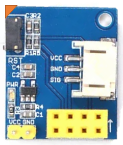
The ESP01 LED Shield, manufactured by Chinases, is a compact and versatile add-on board designed to work seamlessly with the ESP-01 Wi-Fi module. This shield features a built-in LED that can be controlled via the ESP-01, making it ideal for IoT projects, home automation, and educational purposes. It simplifies the process of testing and prototyping with the ESP-01 module by providing a pre-wired LED circuit.

Explore Projects Built with esp01 led shield

Use Cirkit Designer to design, explore, and prototype these projects online. Some projects support real-time simulation. Click "Open Project" to start designing instantly!
ESP8266 NodeMCU Controlled Smart Light with Gesture Sensing and Relay Switching
Image of Class light fan Automation: A project utilizing esp01 led shield in a practical application
This circuit features an ESP8266 NodeMCU microcontroller interfaced with an Adafruit APDS-9960 sensor and a 1-Channel Relay to control a 9W-10W bulb. The APDS-9960 sensor likely provides input to the NodeMCU to trigger the relay, which in turn switches the bulb on or off. A Mini 360 Buck Converter is used to step down voltage for the NodeMCU and sensor, while a pilot lamp indicates the system status.
Cirkit Designer LogoOpen Project in Cirkit Designer
ESP8266 NodeMCU-Based Environmental Monitoring and Proximity Detection System
Image of mgr: A project utilizing esp01 led shield in a practical application
This circuit features an ESP8266 NodeMCU microcontroller interfaced with a BME/BMP280 sensor for environmental data, an HC-SR04 ultrasonic sensor for distance measurement, and an OLED display for output. Two LEDs (red and green) are included, each with a current-limiting resistor, likely for status indication. The ESP8266 facilitates communication with the sensors and display via I2C (SCL and SDA lines) and controls the LEDs and reads from the ultrasonic sensor using its GPIO pins.
Cirkit Designer LogoOpen Project in Cirkit Designer
Wi-Fi Controlled ESP8266 with OLED Display and LED Indicators
Image of Final Project Circuit Rev 1: A project utilizing esp01 led shield in a practical application
This circuit features an ESP8266 NodeMCU microcontroller interfaced with a 0.96" OLED display for visual output and two LEDs (red and green) for status indication. The OLED is connected via I2C (SCK to D1, SDA to D2), while the LEDs are controlled by GPIO pins D3 and D4, with current-limiting resistors in series with the LED cathodes.
Cirkit Designer LogoOpen Project in Cirkit Designer
ESP8266 NodeMCU-Based Environmental Monitoring System with Motion Detection
Image of 1: A project utilizing esp01 led shield in a practical application
This circuit is designed around an ESP8266 NodeMCU microcontroller, interfaced with a DHT22 temperature and humidity sensor, a PIR motion sensor, a TSL2561 lux sensor for light intensity measurement, and an MMWave radar sensor. The ESP8266 reads environmental data from the sensors and can control an RGB LED through PWM outputs. The code provided suggests the circuit is intended for a smart environment monitoring system, possibly for a garage, with capabilities to detect motion, measure light levels, and monitor temperature and humidity.
Cirkit Designer LogoOpen Project in Cirkit Designer

Explore Projects Built with esp01 led shield

Use Cirkit Designer to design, explore, and prototype these projects online. Some projects support real-time simulation. Click "Open Project" to start designing instantly!
Image of Class light fan Automation: A project utilizing esp01 led shield in a practical application
ESP8266 NodeMCU Controlled Smart Light with Gesture Sensing and Relay Switching
This circuit features an ESP8266 NodeMCU microcontroller interfaced with an Adafruit APDS-9960 sensor and a 1-Channel Relay to control a 9W-10W bulb. The APDS-9960 sensor likely provides input to the NodeMCU to trigger the relay, which in turn switches the bulb on or off. A Mini 360 Buck Converter is used to step down voltage for the NodeMCU and sensor, while a pilot lamp indicates the system status.
Cirkit Designer LogoOpen Project in Cirkit Designer
Image of mgr: A project utilizing esp01 led shield in a practical application
ESP8266 NodeMCU-Based Environmental Monitoring and Proximity Detection System
This circuit features an ESP8266 NodeMCU microcontroller interfaced with a BME/BMP280 sensor for environmental data, an HC-SR04 ultrasonic sensor for distance measurement, and an OLED display for output. Two LEDs (red and green) are included, each with a current-limiting resistor, likely for status indication. The ESP8266 facilitates communication with the sensors and display via I2C (SCL and SDA lines) and controls the LEDs and reads from the ultrasonic sensor using its GPIO pins.
Cirkit Designer LogoOpen Project in Cirkit Designer
Image of Final Project Circuit Rev 1: A project utilizing esp01 led shield in a practical application
Wi-Fi Controlled ESP8266 with OLED Display and LED Indicators
This circuit features an ESP8266 NodeMCU microcontroller interfaced with a 0.96" OLED display for visual output and two LEDs (red and green) for status indication. The OLED is connected via I2C (SCK to D1, SDA to D2), while the LEDs are controlled by GPIO pins D3 and D4, with current-limiting resistors in series with the LED cathodes.
Cirkit Designer LogoOpen Project in Cirkit Designer
Image of 1: A project utilizing esp01 led shield in a practical application
ESP8266 NodeMCU-Based Environmental Monitoring System with Motion Detection
This circuit is designed around an ESP8266 NodeMCU microcontroller, interfaced with a DHT22 temperature and humidity sensor, a PIR motion sensor, a TSL2561 lux sensor for light intensity measurement, and an MMWave radar sensor. The ESP8266 reads environmental data from the sensors and can control an RGB LED through PWM outputs. The code provided suggests the circuit is intended for a smart environment monitoring system, possibly for a garage, with capabilities to detect motion, measure light levels, and monitor temperature and humidity.
Cirkit Designer LogoOpen Project in Cirkit Designer

Common Applications and Use Cases

  • IoT projects requiring visual feedback (e.g., status indicators)
  • Home automation systems
  • Educational projects for learning about Wi-Fi modules and LED control
  • Quick prototyping and testing of ESP-01 modules

Technical Specifications

The ESP01 LED Shield is designed to complement the ESP-01 module. Below are its key specifications:

General Specifications

  • Input Voltage: 3.3V (supplied by the ESP-01 module)
  • LED Type: Single onboard LED (color may vary by batch)
  • LED Control Pin: GPIO2 of the ESP-01 module
  • Dimensions: Matches the ESP-01 form factor for easy integration
  • Compatibility: ESP-01 and ESP-01S Wi-Fi modules

Pin Configuration and Descriptions

The ESP01 LED Shield does not have standalone pins but connects directly to the ESP-01 module. Below is the pin mapping for the ESP-01 module when used with the shield:

ESP-01 Pin Function Description
VCC Power Supply Connects to 3.3V power source.
GND Ground Common ground for the circuit.
GPIO2 LED Control Controls the onboard LED.
GPIO0 General Purpose I/O Not used by the shield but available.
RX UART Receive For serial communication (not shield-specific).
TX UART Transmit For serial communication (not shield-specific).
CH_PD Chip Enable Must be pulled high for the ESP-01 to function.
RST Reset Resets the ESP-01 module.

Usage Instructions

How to Use the ESP01 LED Shield in a Circuit

  1. Attach the ESP01 Module: Plug the ESP-01 module into the ESP01 LED Shield. Ensure proper alignment of the pins.
  2. Power the Module: Provide a 3.3V power supply to the ESP-01 module. The shield draws power directly from the ESP-01.
  3. Control the LED:
    • The onboard LED is connected to GPIO2 of the ESP-01 module.
    • Use GPIO2 to turn the LED on or off or to create blinking patterns.

Important Considerations and Best Practices

  • Power Supply: Ensure the ESP-01 module is powered with a stable 3.3V source. Using higher voltages can damage the module and the shield.
  • GPIO2 Usage: Avoid using GPIO2 for other purposes while using the LED shield, as it is dedicated to controlling the onboard LED.
  • Heat Management: The ESP-01 module may heat up during prolonged use. Ensure proper ventilation to avoid overheating.
  • Programming the ESP-01: If you need to reprogram the ESP-01, remove it from the shield and use a USB-to-serial adapter.

Example Code for Arduino UNO

Below is an example of how to control the onboard LED of the ESP01 LED Shield using the Arduino IDE:

// Example code to control the onboard LED of the ESP01 LED Shield
// Ensure the ESP-01 is properly connected to the shield and powered

void setup() {
  pinMode(2, OUTPUT); // Set GPIO2 as an output pin
}

void loop() {
  digitalWrite(2, HIGH); // Turn the LED on
  delay(1000);           // Wait for 1 second
  digitalWrite(2, LOW);  // Turn the LED off
  delay(1000);           // Wait for 1 second
}

Note: Before uploading the code, ensure the ESP-01 is in programming mode and connected to a USB-to-serial adapter.

Troubleshooting and FAQs

Common Issues and Solutions

  1. LED Not Turning On:

    • Cause: GPIO2 is not configured as an output.
    • Solution: Verify your code and ensure pinMode(2, OUTPUT) is included in the setup() function.
  2. ESP-01 Not Powering On:

    • Cause: Insufficient or unstable power supply.
    • Solution: Use a reliable 3.3V power source with adequate current capacity (at least 300mA).
  3. LED Flickering or Dim:

    • Cause: GPIO2 is being used for other purposes or the power supply is unstable.
    • Solution: Ensure GPIO2 is dedicated to LED control and check the power supply.
  4. ESP-01 Not Responding to Commands:

    • Cause: Incorrect wiring or the module is not in programming mode.
    • Solution: Double-check the connections and ensure the ESP-01 is in the correct mode for programming or operation.

FAQs

Q: Can I use the ESP01 LED Shield with other ESP modules?
A: No, the shield is specifically designed for the ESP-01 and ESP-01S modules. It is not compatible with other ESP modules.

Q: Can I control the LED using PWM?
A: Yes, you can use PWM (Pulse Width Modulation) on GPIO2 to control the brightness of the LED.

Q: Is the LED color customizable?
A: The LED color is determined by the manufacturer and cannot be changed without replacing the LED.

Q: Can I use the shield without the LED?
A: Yes, but the onboard LED is hardwired to GPIO2, so it will still consume a small amount of current.

Q: How do I reset the ESP-01 while it is on the shield?
A: Use the RST pin on the ESP-01 module to reset it manually.

This concludes the documentation for the ESP01 LED Shield. For further assistance, refer to the manufacturer's datasheet or support resources.