Cirkit Designer
Your all-in-one circuit design IDE
Home /
Component Documentation
How to Use L298N Motor Driver Controller Board Module Stepper Motor: Examples, Pinouts, and Specs
Introduction
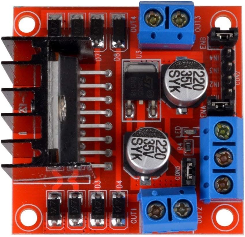
The L298N Motor Driver Controller Board Module by HiLetgo is a versatile and robust dual H-bridge motor driver integrated circuit (IC) designed to control two DC motors or one stepper motor. It is widely used in robotics, DIY projects, and various electronic applications where precise motor control is required. The L298N allows for independent control of speed and direction for each motor, making it an ideal choice for projects that require complex movements.
Explore Projects Built with L298N Motor Driver Controller Board Module Stepper Motor
Arduino Mega 2560 Controlled Multi-Stepper Motor System with SIM800L GSM Module
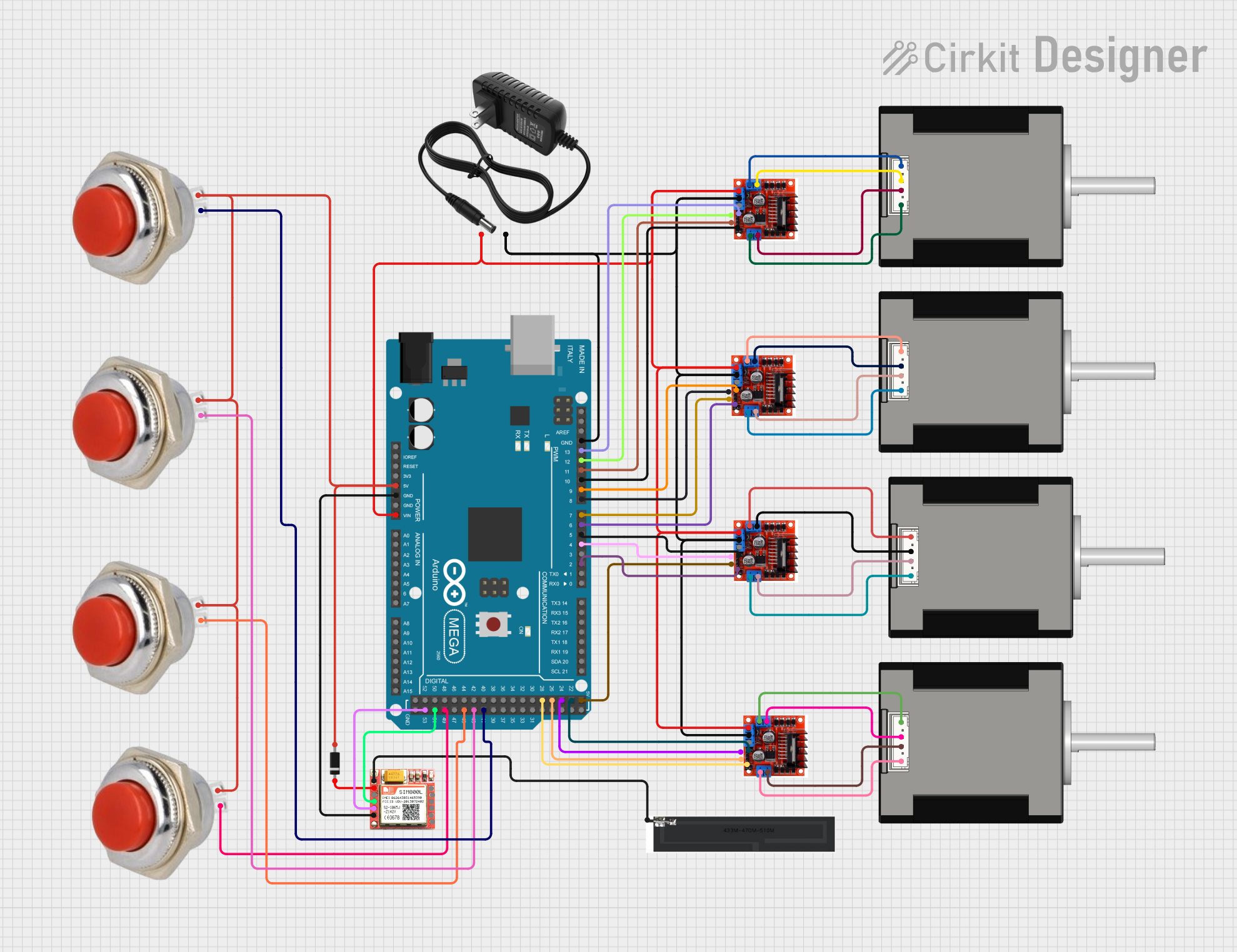
This circuit is designed to control multiple stepper motors using L298N motor driver modules, with an Arduino Mega 2560 serving as the central controller. It features remote communication capabilities via a SIM800L GSM module and user interaction through momentary switches. Protection or control flow is managed by diodes, and a 12V power supply powers the system.
ESP32-Controlled Dual DC Motor & Stepper Motor Driver System
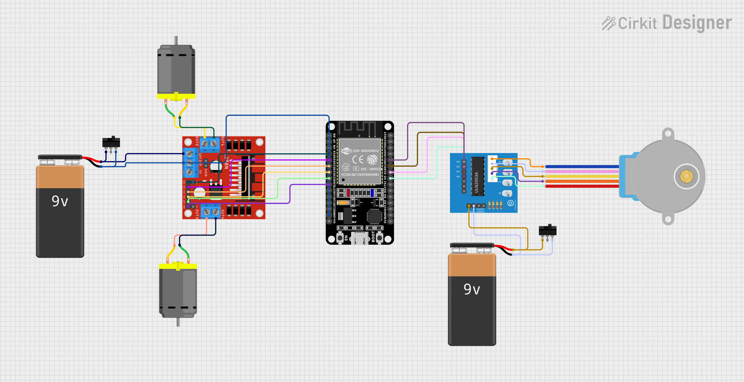
This circuit controls two DC motors and a stepper motor using an ESP32 microcontroller. The L298N motor driver interfaces with the ESP32 to drive the DC motors, allowing for directional control and speed regulation through PWM. Additionally, the ULN2003A breakout board is used to control the 28BYJ-48 stepper motor, with the ESP32 dictating the stepping sequence. Power is supplied by 9V batteries, with toggle switches to control power flow to the motor drivers.
ESP32-Controlled Dual Stepper Motor Driver System
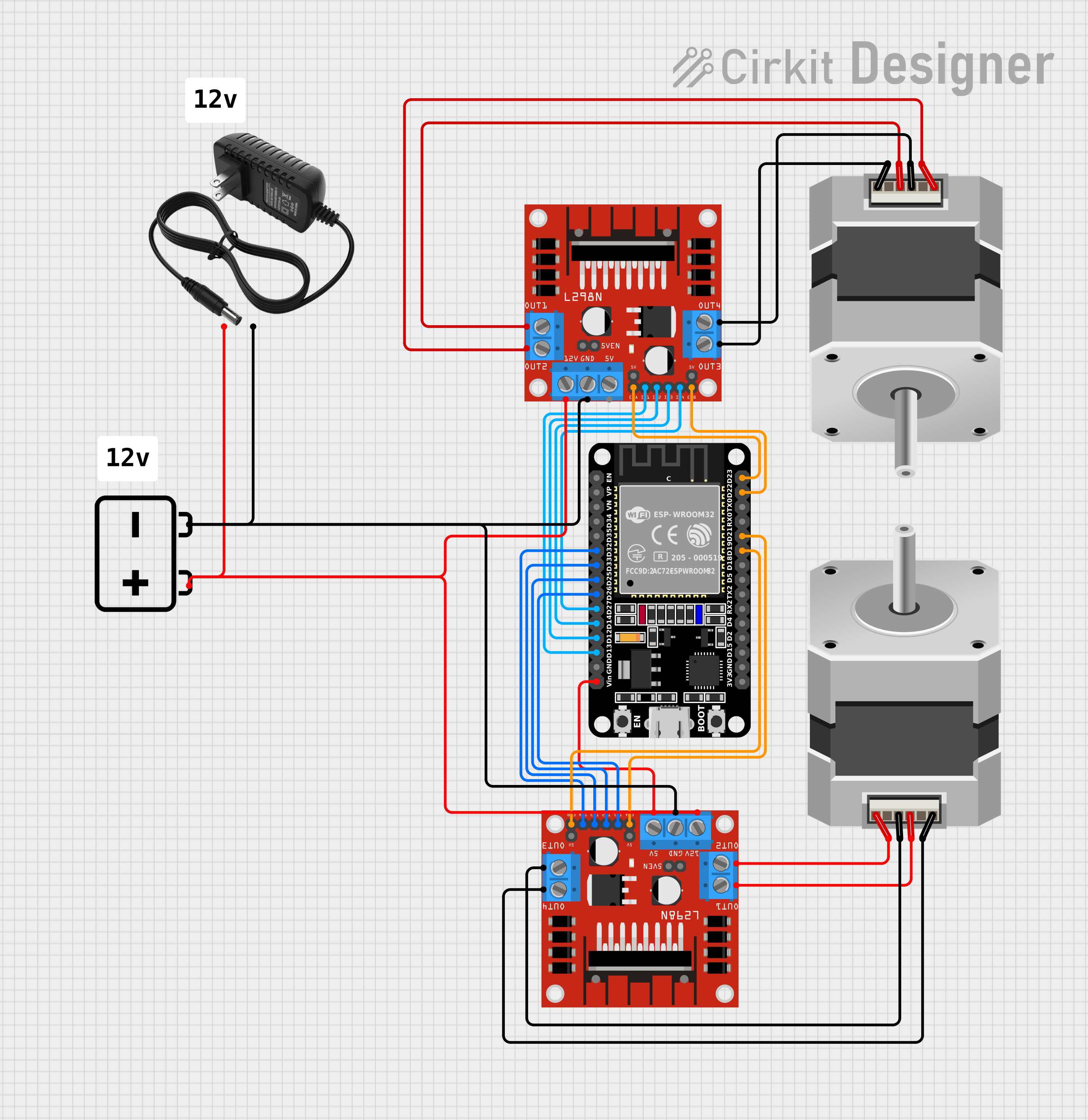
This circuit consists of two L298N DC motor drivers controlled by an ESP32 microcontroller to drive two bipolar stepper motors. The ESP32 uses its GPIO pins to send control signals to the motor drivers, which in turn power the stepper motors with a 12V supply from either a battery or a power supply. The circuit is designed for precise control of stepper motors, likely for applications requiring synchronized movements, such as robotics or CNC machines.
ESP32 and L298N Motor Driver Controlled DC and Stepper Motors with Toggle Switch and Battery Power

This circuit controls two DC motors and a stepper motor using an ESP32 microcontroller. The L298N motor driver is used to drive the DC motors, while the ULN2003A breakout board is used to control the stepper motor. The ESP32 is programmed to manage the motor operations, including direction and speed control.
Explore Projects Built with L298N Motor Driver Controller Board Module Stepper Motor
Arduino Mega 2560 Controlled Multi-Stepper Motor System with SIM800L GSM Module
This circuit is designed to control multiple stepper motors using L298N motor driver modules, with an Arduino Mega 2560 serving as the central controller. It features remote communication capabilities via a SIM800L GSM module and user interaction through momentary switches. Protection or control flow is managed by diodes, and a 12V power supply powers the system.
ESP32-Controlled Dual DC Motor & Stepper Motor Driver System
This circuit controls two DC motors and a stepper motor using an ESP32 microcontroller. The L298N motor driver interfaces with the ESP32 to drive the DC motors, allowing for directional control and speed regulation through PWM. Additionally, the ULN2003A breakout board is used to control the 28BYJ-48 stepper motor, with the ESP32 dictating the stepping sequence. Power is supplied by 9V batteries, with toggle switches to control power flow to the motor drivers.
ESP32-Controlled Dual Stepper Motor Driver System
This circuit consists of two L298N DC motor drivers controlled by an ESP32 microcontroller to drive two bipolar stepper motors. The ESP32 uses its GPIO pins to send control signals to the motor drivers, which in turn power the stepper motors with a 12V supply from either a battery or a power supply. The circuit is designed for precise control of stepper motors, likely for applications requiring synchronized movements, such as robotics or CNC machines.
ESP32 and L298N Motor Driver Controlled DC and Stepper Motors with Toggle Switch and Battery Power
This circuit controls two DC motors and a stepper motor using an ESP32 microcontroller. The L298N motor driver is used to drive the DC motors, while the ULN2003A breakout board is used to control the stepper motor. The ESP32 is programmed to manage the motor operations, including direction and speed control.
Common Applications and Use Cases
- Robotics
- CNC machines
- Automated guided vehicles
- Home automation systems
- DIY electronic projects
Technical Specifications
Key Technical Details
- Operating Voltage (Logic): 5V
- Operating Voltage (Motor Supply): 5V-35V
- Motor Output Current (Max Continuous): 2A per channel
- Peak Output Current (Non-Repetitive): 3A
- Power Dissipation (Max): 25W
Pin Configuration and Descriptions
| Pin Number | Pin Name | Description |
|---|---|---|
| 1 | OUT1 | Motor channel 1 output A |
| 2 | OUT2 | Motor channel 1 output B |
| 3 | OUT3 | Motor channel 2 output A |
| 4 | OUT4 | Motor channel 2 output B |
| 5 | VS | Motor power supply input (5V-35V) |
| 6 | GND | Ground |
| 7 | VSS | Logic power supply input (5V) |
| 8 | IN1 | Control input for motor channel 1A |
| 9 | IN2 | Control input for motor channel 1B |
| 10 | IN3 | Control input for motor channel 2A |
| 11 | IN4 | Control input for motor channel 2B |
| 12 | ENA | PWM input for speed control of motor channel 1 |
| 13 | ENB | PWM input for speed control of motor channel 2 |
Usage Instructions
How to Use the Component in a Circuit
- Connect the motor power supply to the VS and GND pins, ensuring that the voltage is within the specified range.
- Connect the logic power supply to the VSS and GND pins.
- Connect the motors to the OUT1/OUT2 and OUT3/OUT4 pairs.
- Apply PWM signals to ENA and ENB for speed control.
- Use digital signals to IN1, IN2, IN3, and IN4 to set the direction of the motors.
Important Considerations and Best Practices
- Always ensure that the power supply voltage does not exceed the maximum rating.
- Use a separate power supply for the motors and logic when currents are high to prevent noise issues.
- Incorporate flyback diodes if using inductive loads to protect the driver from voltage spikes.
- Avoid running the motor driver at its maximum current rating for extended periods to prevent overheating.
Troubleshooting and FAQs
Common Issues Users Might Face
- Motor not running: Check power supply connections and ensure that the input signals to IN1-IN4 are correct.
- Overheating: Ensure that the current draw is within the limits and consider adding a heat sink if necessary.
- Inconsistent motor speed: Verify that the PWM signal is stable and that the power supply can handle the current draw.
Solutions and Tips for Troubleshooting
- Double-check wiring and solder joints for any loose connections or shorts.
- Use a multimeter to verify the voltage levels at the power inputs and outputs.
- Test the input control signals with an oscilloscope to ensure they are being received correctly by the L298N.
Example Code for Arduino UNO
// Example code to control a DC motor with L298N Motor Driver and Arduino UNO

const int motorPin1 = 8; // IN1 on the L298N
const int motorPin2 = 9; // IN2 on the L298N
const int enablePin = 10; // ENA on the L298N

void setup() {
  pinMode(motorPin1, OUTPUT);
  pinMode(motorPin2, OUTPUT);
  pinMode(enablePin, OUTPUT);
}

void loop() {
  // Set motor direction clockwise
  digitalWrite(motorPin1, HIGH);
  digitalWrite(motorPin2, LOW);

  // Set speed to maximum
  analogWrite(enablePin, 255);

  delay(2000); // Run for 2 seconds

  // Set motor direction counterclockwise
  digitalWrite(motorPin1, LOW);
  digitalWrite(motorPin2, HIGH);

  delay(2000); // Run for 2 seconds

  // Stop the motor
  digitalWrite(motorPin1, LOW);
  digitalWrite(motorPin2, LOW);

  delay(2000); // Stop for 2 seconds
}
Note: The above code is a simple demonstration of controlling a DC motor's direction and speed using the L298N Motor Driver. For more complex applications, additional code and hardware setup may be required.