How to Use 12V Buzzer: Examples, Pinouts, and Specs
Introduction
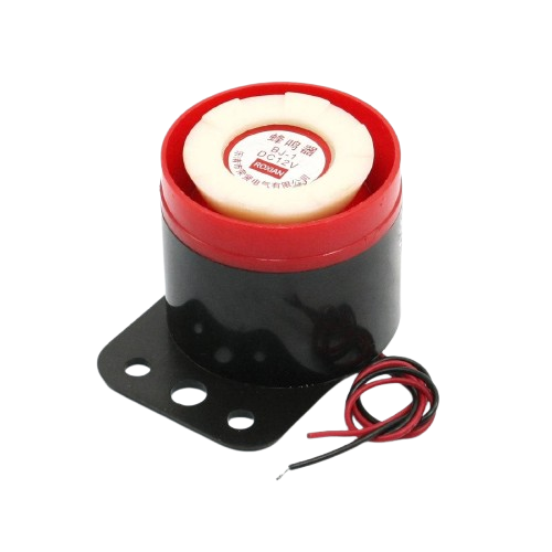
The 12V Buzzer is an electronic device designed to emit a sound when a 12V DC voltage is applied. It is commonly used in various applications such as alarms, notifications, and signaling purposes. This component is essential in systems where audible alerts are necessary to indicate certain conditions or statuses.
Explore Projects Built with 12V Buzzer
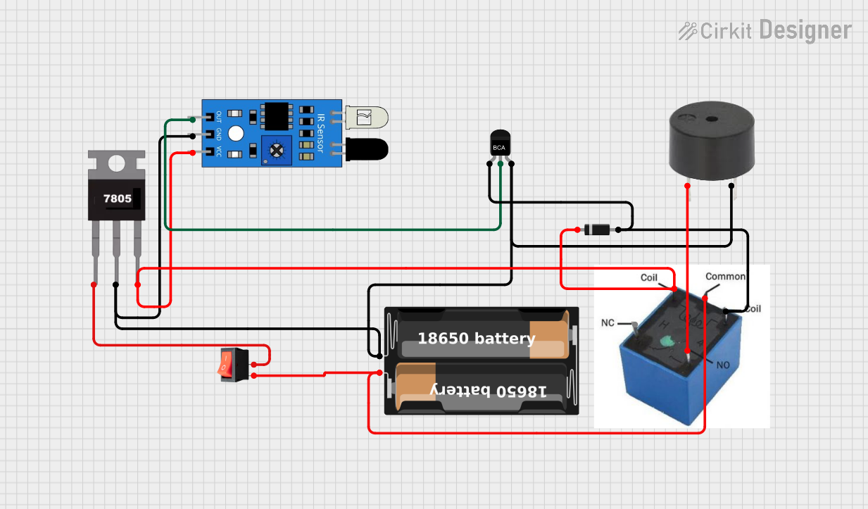
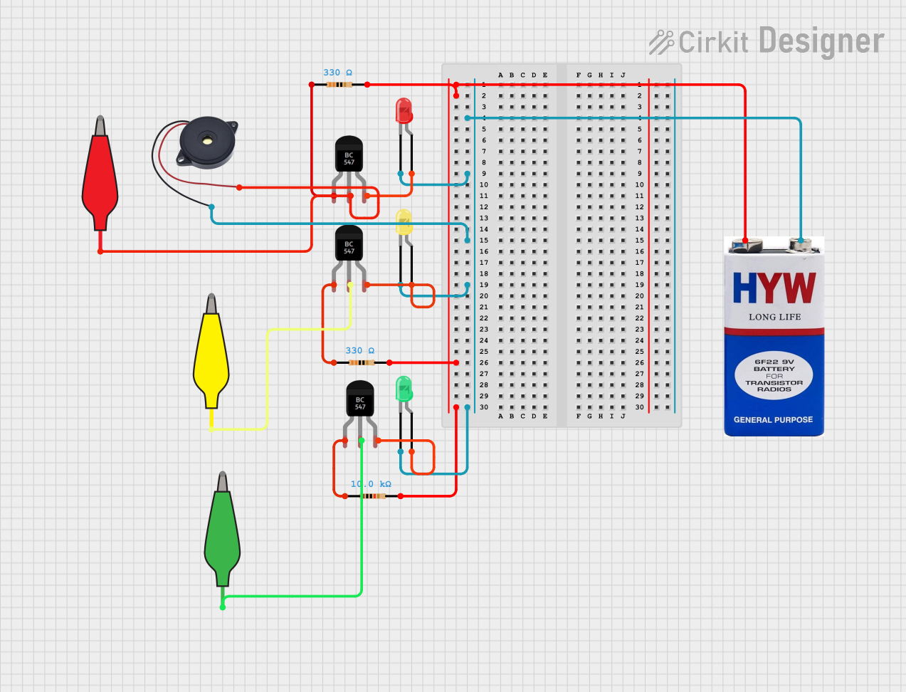

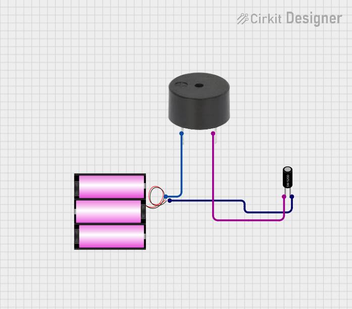
Explore Projects Built with 12V Buzzer
Technical Specifications
Key Technical Details
| Parameter | Value |
|---|---|
| Operating Voltage | 12V DC |
| Current Consumption | 30mA (typical) |
| Sound Output | 85dB @ 10cm |
| Frequency | 2.8kHz |
| Operating Temperature | -20°C to 60°C |
| Dimensions | 30mm x 20mm x 15mm |
Pin Configuration and Descriptions
| Pin Number | Pin Name | Description |
|---|---|---|
| 1 | VCC | Connect to 12V DC power supply |
| 2 | GND | Connect to ground |
Usage Instructions
How to Use the Component in a Circuit
To use the 12V Buzzer in a circuit, follow these steps:
- Power Supply Connection: Connect the VCC pin of the buzzer to a 12V DC power supply.
- Ground Connection: Connect the GND pin of the buzzer to the ground of the power supply.
- Control Signal (Optional): If you want to control the buzzer using a microcontroller (e.g., Arduino), you can use a transistor to switch the buzzer on and off.
Example Circuit Diagram
+12V DC
  |
  |
 [Buzzer]
  |  |
  |  GND
  |
 [NPN Transistor]
  |  |
  |  GND
  |
 [Arduino Digital Pin]
Important Considerations and Best Practices
- Power Supply: Ensure that the power supply provides a stable 12V DC to avoid damaging the buzzer.
- Current Limiting: Although the buzzer typically consumes 30mA, it is good practice to use a current-limiting resistor if the power supply is capable of providing higher currents.
- Mounting: Secure the buzzer properly in your project to avoid vibrations that could affect its performance.
Troubleshooting and FAQs
Common Issues Users Might Face
No Sound Emitted:
- Solution: Check the power supply voltage and ensure it is 12V DC. Verify all connections are secure and correct.
Intermittent Sound:
- Solution: Ensure the power supply is stable and not fluctuating. Check for loose connections.
Low Sound Output:
- Solution: Verify that the buzzer is not obstructed and is mounted correctly. Ensure the power supply is providing the correct voltage.
Solutions and Tips for Troubleshooting
- Check Connections: Always double-check your wiring to ensure all connections are secure and correct.
- Measure Voltage: Use a multimeter to measure the voltage at the buzzer's VCC pin to ensure it is receiving 12V DC.
- Inspect Components: Look for any visible damage to the buzzer or other components in the circuit.
Arduino UNO Example Code
If you are using the 12V Buzzer with an Arduino UNO, you can control it using a digital pin and a transistor. Below is an example code to turn the buzzer on and off:
// Define the pin connected to the transistor base
const int buzzerPin = 9;

void setup() {
  // Set the buzzer pin as an output
  pinMode(buzzerPin, OUTPUT);
}

void loop() {
  // Turn the buzzer on
  digitalWrite(buzzerPin, HIGH);
  delay(1000); // Wait for 1 second

  // Turn the buzzer off
  digitalWrite(buzzerPin, LOW);
  delay(1000); // Wait for 1 second
}
In this example, the buzzer will emit a sound for 1 second and then be silent for 1 second, repeatedly. Ensure you connect the transistor's base to the Arduino pin through a current-limiting resistor (e.g., 1kΩ) to protect the microcontroller.
By following this documentation, you should be able to effectively integrate and troubleshoot the 12V Buzzer in your projects.