Cirkit Designer
Your all-in-one circuit design IDE
Home /
Component Documentation
How to Use Ambient Light Sensor: Examples, Pinouts, and Specs
Introduction
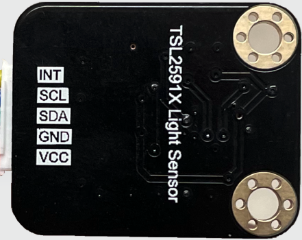
The CQRobot TSL25911FN Ambient Light Sensor is a highly sensitive device designed to measure the intensity of light in the surrounding environment and convert it into an electrical signal. This sensor is ideal for applications requiring precise light measurements, such as in smartphones, tablets, and other portable devices, as well as in industrial and environmental monitoring systems.
Explore Projects Built with Ambient Light Sensor
Arduino-Based Light Level Monitor with I2C LCD Display
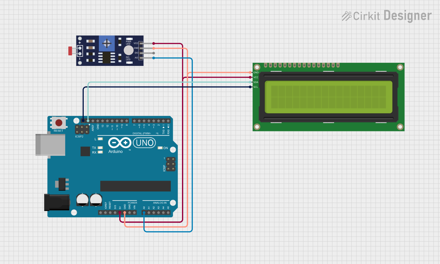
This circuit utilizes a Photoresistor (LDR) sensor to measure ambient light levels and display the results on a 16x2 I2C LCD. The Arduino UNO processes the sensor data and updates the LCD to indicate whether the environment is 'Light' or 'Dark' based on the calculated lux value.
Arduino Nano Controlled Ambient Light Sensing and NeoPixel Display
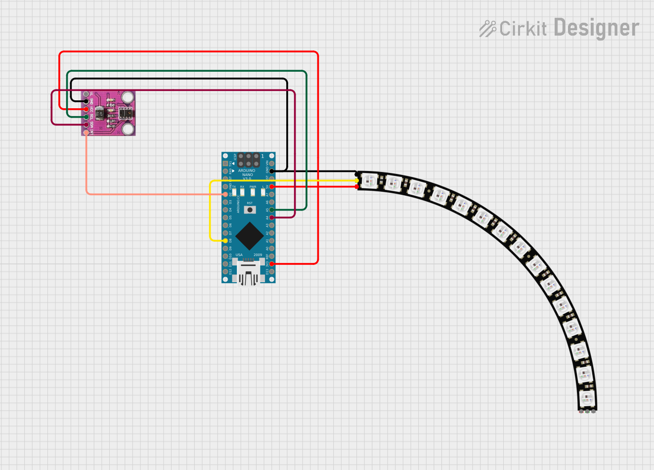
This circuit features an Arduino Nano microcontroller interfaced with an APDS-9930 Proximity and Ambient Light Sensor for sensing environmental light and proximity. The Arduino Nano also controls an Adafruit Quarter 60 NeoPixel Ring, likely for visual feedback or display purposes. The sensor communicates with the Arduino via I2C (SDA and SCL connections), and the NeoPixel Ring is driven by a digital output (D8) from the Arduino.
ESP32-Based Ambient Light Sensing System

This circuit integrates an ESP32 Wroom microcontroller with an APDS-9930 Proximity and Ambient Light Sensor. The ESP32 provides power to the sensor and communicates with it via I2C, using its GPIO21/SDA and GPIO22/SCL pins for data transfer. The circuit is designed to measure proximity and ambient light levels, which can be processed and utilized by the ESP32 for various applications.
Raspberry Pi 5 Ambient Light Sensor System
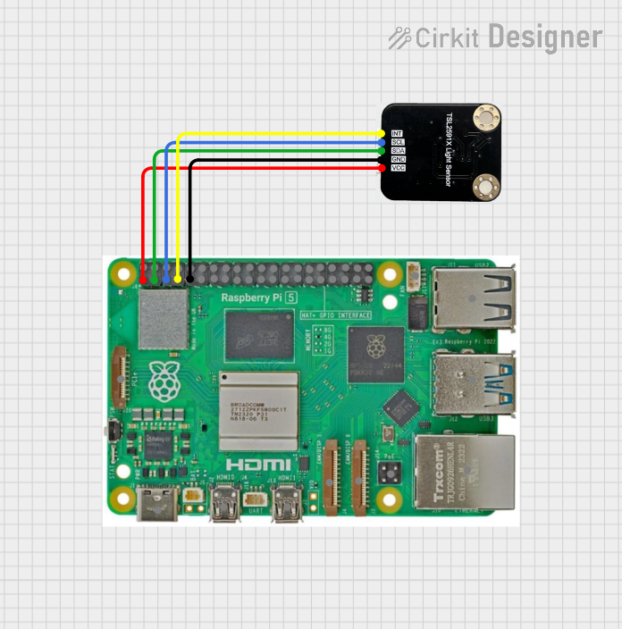
This circuit connects a Raspberry Pi 5 to an ambient light sensor. The Raspberry Pi provides power and ground to the sensor, and communicates with it using I2C protocol through GPIO pins 2 (SDA) and 3 (SCL), with an interrupt line connected to GPIO pin 4.
Explore Projects Built with Ambient Light Sensor
Arduino-Based Light Level Monitor with I2C LCD Display
This circuit utilizes a Photoresistor (LDR) sensor to measure ambient light levels and display the results on a 16x2 I2C LCD. The Arduino UNO processes the sensor data and updates the LCD to indicate whether the environment is 'Light' or 'Dark' based on the calculated lux value.
Arduino Nano Controlled Ambient Light Sensing and NeoPixel Display
This circuit features an Arduino Nano microcontroller interfaced with an APDS-9930 Proximity and Ambient Light Sensor for sensing environmental light and proximity. The Arduino Nano also controls an Adafruit Quarter 60 NeoPixel Ring, likely for visual feedback or display purposes. The sensor communicates with the Arduino via I2C (SDA and SCL connections), and the NeoPixel Ring is driven by a digital output (D8) from the Arduino.
ESP32-Based Ambient Light Sensing System
This circuit integrates an ESP32 Wroom microcontroller with an APDS-9930 Proximity and Ambient Light Sensor. The ESP32 provides power to the sensor and communicates with it via I2C, using its GPIO21/SDA and GPIO22/SCL pins for data transfer. The circuit is designed to measure proximity and ambient light levels, which can be processed and utilized by the ESP32 for various applications.
Raspberry Pi 5 Ambient Light Sensor System
This circuit connects a Raspberry Pi 5 to an ambient light sensor. The Raspberry Pi provides power and ground to the sensor, and communicates with it using I2C protocol through GPIO pins 2 (SDA) and 3 (SCL), with an interrupt line connected to GPIO pin 4.
Technical Specifications
Key Technical Details
| Parameter | Value |
|---|---|
| Manufacturer | CQRobot |
| Part ID | TSL25911FN |
| Supply Voltage | 2.7V to 3.6V |
| Operating Current | 0.6mA (typical) |
| Lux Range | 188 µLux to 88,000 Lux |
| Interface | I2C |
| Operating Temperature | -30°C to 80°C |
| Package | FN (6-pin) |
Pin Configuration and Descriptions
| Pin Number | Pin Name | Description |
|---|---|---|
| 1 | VDD | Power supply (2.7V to 3.6V) |
| 2 | GND | Ground |
| 3 | SDA | I2C data line |
| 4 | SCL | I2C clock line |
| 5 | INT | Interrupt output (active low) |
| 6 | ADDR | I2C address select (connect to GND or VDD) |
Usage Instructions
How to Use the Component in a Circuit
- Power Supply: Connect the VDD pin to a 3.3V power supply and the GND pin to the ground.
- I2C Communication: Connect the SDA pin to the SDA line of your microcontroller and the SCL pin to the SCL line.
- I2C Address Selection: Connect the ADDR pin to GND for the default I2C address (0x29) or to VDD for an alternate address (0x28).
- Interrupt Pin: Optionally, connect the INT pin to a digital input on your microcontroller to handle interrupts.
Important Considerations and Best Practices
- Power Supply: Ensure the power supply voltage is within the specified range (2.7V to 3.6V) to avoid damaging the sensor.
- I2C Pull-up Resistors: Use appropriate pull-up resistors (typically 4.7kΩ) on the SDA and SCL lines to ensure proper I2C communication.
- Ambient Light: Place the sensor in a location where it can accurately measure the ambient light without obstructions.
Example Code for Arduino UNO
#include <Wire.h>

// TSL25911FN I2C address
#define TSL25911FN_ADDR 0x29

void setup() {
  Serial.begin(9600);
  Wire.begin(); // Initialize I2C communication

  // Initialize the TSL25911FN sensor
  Wire.beginTransmission(TSL25911FN_ADDR);
  Wire.write(0x00); // Command register
  Wire.write(0x03); // Power on the sensor
  Wire.endTransmission();
}

void loop() {
  uint16_t ch0, ch1;

  // Read channel 0 (visible + IR)
  Wire.beginTransmission(TSL25911FN_ADDR);
  Wire.write(0x14); // Data register for channel 0
  Wire.endTransmission();
  Wire.requestFrom(TSL25911FN_ADDR, 2);
  ch0 = Wire.read();
  ch0 |= (Wire.read() << 8);

  // Read channel 1 (IR only)
  Wire.beginTransmission(TSL25911FN_ADDR);
  Wire.write(0x16); // Data register for channel 1
  Wire.endTransmission();
  Wire.requestFrom(TSL25911FN_ADDR, 2);
  ch1 = Wire.read();
  ch1 |= (Wire.read() << 8);

  // Calculate lux (simplified formula)
  float lux = (ch0 - ch1) * (1.0 / 0.39);

  Serial.print("Lux: ");
  Serial.println(lux);

  delay(1000); // Wait for 1 second before next reading
}
Troubleshooting and FAQs
Common Issues Users Might Face
- No I2C Communication: Ensure the SDA and SCL lines are correctly connected and that pull-up resistors are used.
- Incorrect Lux Readings: Verify that the sensor is not obstructed and is placed in an appropriate location for accurate light measurement.
- Sensor Not Powering On: Check the power supply voltage and connections to the VDD and GND pins.
Solutions and Tips for Troubleshooting
- Check Connections: Double-check all wiring and connections to ensure they are secure and correct.
- Use a Multimeter: Measure the voltage at the VDD pin to ensure it is within the specified range.
- Verify I2C Address: Ensure the correct I2C address is used in the code, based on the ADDR pin connection.
By following this documentation, users can effectively integrate and utilize the CQRobot TSL25911FN Ambient Light Sensor in their projects, ensuring accurate and reliable light measurements.