How to Use HX711: Examples, Pinouts, and Specs
Introduction
The HX711 is a precision 24-bit analog-to-digital converter (ADC) designed for applications requiring high accuracy and stability, such as weigh scales and industrial control systems. It is widely used to interface with load cells, converting the small analog signals from the load cell into a digital format that can be processed by microcontrollers. The HX711 simplifies the design of weighing systems by integrating a low-noise programmable gain amplifier (PGA) and a high-resolution ADC in a single package.
Explore Projects Built with HX711

Explore Projects Built with HX711
Common Applications and Use Cases
- Digital weigh scales
- Industrial process control systems
- Force measurement systems
- IoT-based weight monitoring
- Laboratory equipment requiring precise weight measurements
Technical Specifications
The HX711 is a highly integrated ADC with the following key specifications:
| Parameter | Value |
|---|---|
| Supply Voltage | 2.6V to 5.5V |
| Operating Current | ~1.5mA |
| Standby Current | <1µA |
| ADC Resolution | 24-bit |
| Input Channels | 2 (Channel A and Channel B) |
| Programmable Gain | 32, 64, or 128 |
| Data Rate | 10 Hz or 80 Hz |
| Input Voltage Range | ±40mV (at Gain = 128) |
| Operating Temperature Range | -40°C to +85°C |
| Package Type | SOP-16 |
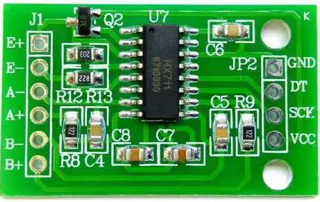
Pin Configuration and Descriptions
The HX711 has 16 pins, but only a subset is typically used in most applications. Below is the pin configuration:
| Pin Number | Pin Name | Description |
|---|---|---|
| 1 | E+ | Positive excitation voltage for the load cell |
| 2 | E- | Negative excitation voltage for the load cell |
| 3 | A+ | Positive input for Channel A |
| 4 | A- | Negative input for Channel A |
| 5 | B+ | Positive input for Channel B |
| 6 | B- | Negative input for Channel B |
| 7 | AVDD | Analog power supply |
| 8 | AGND | Analog ground |
| 9 | DGND | Digital ground |
| 10 | PD_SCK | Power-down and serial clock input |
| 11 | DOUT | Serial data output |
| 12 | DVDD | Digital power supply |
| 13-16 | NC | Not connected |
Usage Instructions
How to Use the HX711 in a Circuit
- Power Supply: Connect the HX711 to a stable power source (2.6V to 5.5V). Use AVDD and DVDD for analog and digital power, respectively, and connect AGND and DGND to ground.
- Load Cell Connection:
- Connect the load cell's excitation wires to E+ and E-.
- Connect the load cell's signal wires to A+ and A- (for Channel A) or B+ and B- (for Channel B).
- Microcontroller Interface:
- Connect the
PD_SCKpin to a GPIO pin on the microcontroller for clock signals. - Connect the
DOUTpin to another GPIO pin for reading data.
- Connect the
- Data Reading:
- Use the
PD_SCKpin to control the data output rate (10 Hz or 80 Hz). - Read the 24-bit digital output from the
DOUTpin.
- Use the
Important Considerations and Best Practices
- Gain Selection: Channel A supports programmable gains of 128 and 64, while Channel B has a fixed gain of 32. Use Channel A for higher precision.
- Noise Reduction: To minimize noise, use proper decoupling capacitors and shielded cables for the load cell.
- Power-Down Mode: To save power, pull the
PD_SCKpin high for at least 60µs to enter power-down mode. - Data Timing: Ensure proper timing when reading data from the
DOUTpin. The data is clocked out on the falling edge ofPD_SCK.
Example Code for Arduino UNO
Below is an example of how to interface the HX711 with an Arduino UNO to read data from a load cell:
#include "HX711.h" // Include the HX711 library

// Define HX711 pins
#define DOUT  3  // Data output pin connected to Arduino pin 3
#define SCK   2  // Clock pin connected to Arduino pin 2

HX711 scale; // Create an instance of the HX711 class

void setup() {
  Serial.begin(9600); // Initialize serial communication
  scale.begin(DOUT, SCK); // Initialize the HX711 with the defined pins
  scale.set_scale(); // Set the scale factor (calibration required)
  scale.tare(); // Reset the scale to zero
  Serial.println("HX711 initialized. Place weight on the scale.");
}

void loop() {
  if (scale.is_ready()) { // Check if the HX711 is ready
    long reading = scale.get_units(); // Get the weight in units
    Serial.print("Weight: ");
    Serial.print(reading);
    Serial.println(" units");
  } else {
    Serial.println("HX711 not ready. Check connections.");
  }
  delay(500); // Wait for 500ms before the next reading
}
Notes on Calibration
- The
set_scale()function in the code above requires a calibration factor. This factor is determined by placing a known weight on the load cell and adjusting the value until the correct weight is displayed.
Troubleshooting and FAQs
Common Issues and Solutions
No Data Output:
- Cause: Incorrect wiring or loose connections.
- Solution: Verify all connections, especially
DOUTandPD_SCK.
Unstable Readings:
- Cause: Electrical noise or insufficient shielding.
- Solution: Use shielded cables for the load cell and add decoupling capacitors near the HX711.
Incorrect Weight Measurements:
- Cause: Improper calibration.
- Solution: Recalibrate the scale using a known weight and adjust the scale factor.
HX711 Not Responding:
- Cause: Power supply issues or incorrect clock timing.
- Solution: Ensure the power supply is stable and verify the timing of
PD_SCKpulses.
FAQs
Q: Can I use the HX711 with a 3.3V microcontroller?
A: Yes, the HX711 operates with a supply voltage as low as 2.6V, making it compatible with 3.3V systems.Q: How do I switch between 10 Hz and 80 Hz data rates?
A: The data rate is determined by the state of theRATEpin. Refer to the HX711 datasheet for details.Q: Can I use both channels (A and B) simultaneously?
A: Yes, but note that Channel A supports higher gain (128 or 64), while Channel B has a fixed gain of 32.Q: What is the maximum weight the HX711 can measure?
A: The maximum weight depends on the load cell used. The HX711 itself measures the voltage output from the load cell, so ensure the load cell's capacity matches your application.
By following this documentation, you can effectively integrate the HX711 into your projects for precise weight measurement and control.