How to Use RYLR896 Lora Module: Examples, Pinouts, and Specs
Introduction
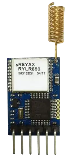
The RYLR896 is a low-power, long-range wireless communication module manufactured by REYAX. It operates on the LoRa (Long Range) protocol, which is known for its ability to transmit data over several kilometers while consuming minimal power. This makes the RYLR896 an ideal choice for Internet of Things (IoT) applications where energy efficiency and long-range communication are critical.
Explore Projects Built with RYLR896 Lora Module


Explore Projects Built with RYLR896 Lora Module
Common Applications and Use Cases
- Remote Sensing: Environmental monitoring, weather stations, and industrial sensors.
- Smart Agriculture: Soil moisture monitoring, livestock tracking, and irrigation systems.
- Smart Cities: Street lighting control, parking management, and waste management.
- Asset Tracking: Logistics, fleet management, and inventory tracking.
- Home Automation: Wireless control of appliances and security systems.
Technical Specifications
The RYLR896 module is designed to provide reliable and efficient communication. Below are its key technical details:
General Specifications
| Parameter | Value |
|---|---|
| Manufacturer | REYAX |
| Part Number | RYLR896 |
| Communication Protocol | LoRa |
| Frequency Range | 868 MHz / 915 MHz |
| Modulation | LoRa Modulation (Spread Spectrum) |
| Data Rate | 0.3 kbps to 37.5 kbps |
| Transmission Range | Up to 15 km (line of sight) |
| Operating Voltage | 2.8V to 3.6V |
| Operating Current | 10.5 mA (transmit), 0.5 µA (sleep mode) |
| Operating Temperature | -40°C to +85°C |
| Dimensions | 15 mm x 22 mm x 3 mm |
Pin Configuration and Descriptions
The RYLR896 module has a total of 12 pins. Below is the pinout and description:
| Pin Number | Pin Name | Description |
|---|---|---|
| 1 | VCC | Power supply input (2.8V to 3.6V) |
| 2 | GND | Ground |
| 3 | TXD | UART Transmit Pin |
| 4 | RXD | UART Receive Pin |
| 5 | RESET | Module Reset (Active Low) |
| 6 | NC | Not Connected |
| 7 | NC | Not Connected |
| 8 | NC | Not Connected |
| 9 | NC | Not Connected |
| 10 | NC | Not Connected |
| 11 | NC | Not Connected |
| 12 | ANT | Antenna Connection |
Usage Instructions
The RYLR896 module is straightforward to integrate into a circuit. It communicates via UART, making it compatible with microcontrollers such as the Arduino UNO.
Steps to Use the RYLR896 in a Circuit
- Power the Module: Connect the VCC pin to a 3.3V power source and the GND pin to ground.
- Connect UART Pins:
- Connect the TXD pin of the module to the RX pin of the microcontroller.
- Connect the RXD pin of the module to the TX pin of the microcontroller.
- Attach an Antenna: Connect a suitable antenna to the ANT pin for optimal signal transmission and reception.
- Reset the Module: Use the RESET pin to initialize the module if needed.
- Send AT Commands: Use a serial terminal or microcontroller to send AT commands to configure and operate the module.
Important Considerations and Best Practices
- Voltage Levels: Ensure the module operates within its voltage range (2.8V to 3.6V). Use a level shifter if interfacing with a 5V microcontroller.
- Antenna Placement: Place the antenna in an open area, away from metal objects, to maximize range.
- Baud Rate: The default UART baud rate is 9600 bps. Configure your microcontroller accordingly.
- Error Handling: Implement error-checking mechanisms in your code to handle communication failures.
Example Code for Arduino UNO
Below is an example of how to use the RYLR896 module with an Arduino UNO:
#include <SoftwareSerial.h>

// Define RX and TX pins for SoftwareSerial
SoftwareSerial loraSerial(10, 11); // RX = Pin 10, TX = Pin 11

void setup() {
  // Initialize Serial Monitor
  Serial.begin(9600);
  while (!Serial);

  // Initialize LoRa Module Serial Communication
  loraSerial.begin(9600);
  Serial.println("RYLR896 LoRa Module Initialized");

  // Send AT command to check module status
  loraSerial.println("AT");
}

void loop() {
  // Check for data from the LoRa module
  if (loraSerial.available()) {
    String response = loraSerial.readString();
    Serial.print("LoRa Module Response: ");
    Serial.println(response);
  }

  // Send a test message every 5 seconds
  static unsigned long lastSendTime = 0;
  if (millis() - lastSendTime > 5000) {
    lastSendTime = millis();
    loraSerial.println("AT+SEND=0,5,Hello");
    Serial.println("Sent: Hello");
  }
}
Explanation of the Code
- SoftwareSerial: Used to communicate with the RYLR896 module on pins 10 and 11.
- AT Command: The
ATcommand checks if the module is responsive. - AT+SEND: Sends a message ("Hello") to the LoRa network.
Troubleshooting and FAQs
Common Issues and Solutions
No Response from the Module
- Cause: Incorrect wiring or baud rate mismatch.
- Solution: Double-check the connections and ensure the baud rate is set to 9600 bps.
Short Communication Range
- Cause: Poor antenna placement or interference.
- Solution: Use a high-quality antenna and place it in an open area.
Module Not Powering On
- Cause: Insufficient power supply.
- Solution: Ensure the power supply provides 3.3V and sufficient current.
AT Commands Not Recognized
- Cause: Incorrect UART configuration.
- Solution: Verify the TX and RX connections and ensure the microcontroller's UART settings match the module.
FAQs
Q: Can the RYLR896 module communicate with other LoRa devices?
A: Yes, as long as the devices operate on the same frequency and use compatible settings.Q: What is the maximum data payload size?
A: The maximum payload size is 240 bytes.Q: Can I use the RYLR896 with a 5V microcontroller?
A: Yes, but you must use a level shifter to convert the 5V signals to 3.3V.Q: How do I change the frequency of the module?
A: Use theAT+FREQ=<frequency>command to set the desired frequency.
This concludes the documentation for the RYLR896 LoRa Module. For further details, refer to the manufacturer's datasheet.