
How to Use Emergency Alarm: Examples, Pinouts, and Specs
 Design with Emergency Alarm in Cirkit Designer
Introduction
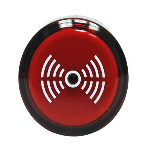
The Emergency Alarm is a device designed to alert individuals to an emergency situation. It typically produces a loud sound, a visual signal, or both, to prompt immediate action. Emergency alarms are widely used in various environments, including residential, commercial, and industrial settings, to ensure safety and quick response during critical situations.
Explore Projects Built with Emergency Alarm
 Open Project in Cirkit Designer
 Open Project in Cirkit Designer
 Open Project in Cirkit Designer
 Open Project in Cirkit Designer
Explore Projects Built with Emergency Alarm
Open Project in Cirkit DesignerOpen Project in Cirkit DesignerOpen Project in Cirkit DesignerOpen Project in Cirkit DesignerCommon Applications and Use Cases
- Fire alarm systems in buildings
- Security systems for unauthorized access detection
- Industrial machinery fault alerts
- Emergency evacuation systems
- Personal safety devices
Technical Specifications
Key Technical Details
| Parameter | Specification |
|---|---|
| Operating Voltage | 5V to 12V DC |
| Current Consumption | 100mA to 300mA (depending on model) |
| Sound Output Level | 85dB to 120dB at 1 meter |
| Visual Signal Type | LED or strobe light (optional) |
| Operating Temperature | -10°C to 50°C |
| Dimensions | Varies by model (e.g., 50mm x 50mm x 30mm) |
Pin Configuration and Descriptions
| Pin Number | Pin Name | Description |
|---|---|---|
| 1 | VCC | Positive power supply (5V to 12V DC) |
| 2 | GND | Ground connection |
| 3 | Signal Input | Trigger input to activate the alarm (HIGH signal) |
Usage Instructions
How to Use the Component in a Circuit
- Power Supply: Connect the
VCCpin to a 5V to 12V DC power source and theGNDpin to the ground of the circuit. - Trigger Signal: Use a microcontroller, such as an Arduino UNO, or a simple switch to provide a HIGH signal to the
Signal Inputpin to activate the alarm. - Output: When the
Signal Inputpin receives a HIGH signal, the alarm will produce a loud sound and, if equipped, a visual signal.
Important Considerations and Best Practices
- Power Requirements: Ensure the power supply matches the operating voltage range of the alarm to avoid damage.
- Signal Input: Use a pull-down resistor on the
Signal Inputpin to prevent false triggering due to floating signals. - Placement: Install the alarm in a location where the sound and/or visual signal can be easily noticed.
- Testing: Periodically test the alarm to ensure it is functioning correctly.
- Safety: Avoid prolonged exposure to the alarm's sound output, as it may cause hearing damage.
Example: Connecting to an Arduino UNO
Below is an example of how to connect and control the Emergency Alarm using an Arduino UNO.
Circuit Connections
- Connect the
VCCpin of the alarm to the 5V pin on the Arduino. - Connect the
GNDpin of the alarm to the GND pin on the Arduino. - Connect the
Signal Inputpin of the alarm to digital pin 8 on the Arduino.
Arduino Code
// Emergency Alarm Control with Arduino UNO
// This code activates the alarm for 5 seconds when triggered.

const int alarmPin = 8; // Pin connected to the Signal Input of the alarm

void setup() {
  pinMode(alarmPin, OUTPUT); // Set the alarm pin as an output
  digitalWrite(alarmPin, LOW); // Ensure the alarm is off initially
}

void loop() {
  // Example: Activate the alarm for 5 seconds
  digitalWrite(alarmPin, HIGH); // Turn on the alarm
  delay(5000); // Keep the alarm on for 5 seconds
  digitalWrite(alarmPin, LOW); // Turn off the alarm
  delay(10000); // Wait for 10 seconds before repeating
}
Troubleshooting and FAQs
Common Issues and Solutions
Alarm Does Not Activate
- Cause: Incorrect wiring or insufficient power supply.
- Solution: Double-check the connections and ensure the power supply matches the required voltage.
False Triggering
- Cause: Floating
Signal Inputpin. - Solution: Use a pull-down resistor (e.g., 10kΩ) on the
Signal Inputpin to stabilize the signal.
- Cause: Floating
Low Sound Output
- Cause: Insufficient voltage or damaged speaker.
- Solution: Verify the power supply voltage and inspect the alarm for physical damage.
Overheating
- Cause: Prolonged operation or excessive current draw.
- Solution: Limit the activation duration and ensure proper ventilation.
FAQs
Q: Can I use the Emergency Alarm with a 3.3V microcontroller?
A: Yes, but you will need a transistor or relay to step up the signal voltage to the alarm's operating range (5V to 12V).
Q: Is the alarm waterproof?
A: Most models are not waterproof. Check the manufacturer's specifications for IP-rated waterproof alarms if needed.
Q: Can I adjust the sound level of the alarm?
A: Some models allow sound level adjustment via a built-in potentiometer. Refer to the specific model's datasheet for details.
Q: How do I test the alarm without a microcontroller?
A: You can manually trigger the alarm by connecting the Signal Input pin to the VCC pin using a switch or jumper wire.