Cirkit Designer Logo
Cirkit Designer
Your all-in-one circuit design IDE
Home / 
Component Documentation

How to Use A4988 Stepper Motor Driver Carrier: Examples, Pinouts, and Specs

Image of A4988 Stepper Motor Driver Carrier
Cirkit Designer LogoDesign with A4988 Stepper Motor Driver Carrier in Cirkit Designer

Introduction

The A4988 Stepper Motor Driver Carrier is a compact module designed to control bipolar stepper motors in full-, half-, quarter-, eighth-, and sixteenth-step modes. It operates with a logic voltage of 3-5.5V and can deliver up to approximately 1A per phase without a heat sink or forced air flow (it is rated for up to 2A per coil with sufficient additional cooling). This driver is an ideal choice for 3D printers, CNC machines, and other applications that require precise control of stepper motors.

Explore Projects Built with A4988 Stepper Motor Driver Carrier

Use Cirkit Designer to design, explore, and prototype these projects online. Some projects support real-time simulation. Click "Open Project" to start designing instantly!
A4988 Stepper Motor Driver Controlled Bipolar Stepper Motor
Image of idk: A project utilizing A4988 Stepper Motor Driver Carrier in a practical application
This circuit is designed to control a bipolar stepper motor using an A4988 stepper motor driver. The driver interfaces with the motor by connecting its output pins to the motor's coils, allowing precise control of the motor's movement.
Cirkit Designer LogoOpen Project in Cirkit Designer
RFID-Activated Traffic Light Controller with Auditory Feedback Using Arduino Mega
Image of test: A project utilizing A4988 Stepper Motor Driver Carrier in a practical application
This circuit is designed to control two 28BYJ-48 stepper motors using A4988 stepper motor driver carriers, with an Arduino Mega 2560 as the central microcontroller. It includes an RFID-RC522 module for RFID reading, an LCD display for user interface, and a traffic light and piezo speaker for visual and audio signaling. The circuit is powered by a 12V 5A power supply, which is stepped down to 5V for logic level components, and it interfaces with a power outlet for AC to DC conversion.
Cirkit Designer LogoOpen Project in Cirkit Designer
Arduino Mega 2560-Controlled Stepper Motors with RFID Access and Traffic Light Indication
Image of Copy of test: A project utilizing A4988 Stepper Motor Driver Carrier in a practical application
This circuit controls two 28BYJ-48 stepper motors using A4988 stepper motor driver carriers, interfaced with an Arduino Mega 2560 microcontroller. It features an RFID-RC522 module for RFID reading, a 16x4 LCD display with I2C interface for user interaction, and a piezo speaker for audio feedback. Additionally, there is a traffic light module controlled by the Arduino, and a 48V to 5V converter to step down voltage for the logic levels. The power supply provides 12V to the motor drivers and is connected to a standard power outlet.
Cirkit Designer LogoOpen Project in Cirkit Designer
Arduino-Controlled Dual Stepper Motor Driver with Boost Converter and User Input
Image of OpenClino: A project utilizing A4988 Stepper Motor Driver Carrier in a practical application
This is a dual stepper motor control circuit using an Arduino Nano to drive two A4988 stepper motor drivers. It includes a boost converter for voltage regulation, an electrolytic capacitor for stability, and an arcade button for user interaction.
Cirkit Designer LogoOpen Project in Cirkit Designer

Explore Projects Built with A4988 Stepper Motor Driver Carrier

Use Cirkit Designer to design, explore, and prototype these projects online. Some projects support real-time simulation. Click "Open Project" to start designing instantly!
Image of idk: A project utilizing A4988 Stepper Motor Driver Carrier in a practical application
A4988 Stepper Motor Driver Controlled Bipolar Stepper Motor
This circuit is designed to control a bipolar stepper motor using an A4988 stepper motor driver. The driver interfaces with the motor by connecting its output pins to the motor's coils, allowing precise control of the motor's movement.
Cirkit Designer LogoOpen Project in Cirkit Designer
Image of test: A project utilizing A4988 Stepper Motor Driver Carrier in a practical application
RFID-Activated Traffic Light Controller with Auditory Feedback Using Arduino Mega
This circuit is designed to control two 28BYJ-48 stepper motors using A4988 stepper motor driver carriers, with an Arduino Mega 2560 as the central microcontroller. It includes an RFID-RC522 module for RFID reading, an LCD display for user interface, and a traffic light and piezo speaker for visual and audio signaling. The circuit is powered by a 12V 5A power supply, which is stepped down to 5V for logic level components, and it interfaces with a power outlet for AC to DC conversion.
Cirkit Designer LogoOpen Project in Cirkit Designer
Image of Copy of test: A project utilizing A4988 Stepper Motor Driver Carrier in a practical application
Arduino Mega 2560-Controlled Stepper Motors with RFID Access and Traffic Light Indication
This circuit controls two 28BYJ-48 stepper motors using A4988 stepper motor driver carriers, interfaced with an Arduino Mega 2560 microcontroller. It features an RFID-RC522 module for RFID reading, a 16x4 LCD display with I2C interface for user interaction, and a piezo speaker for audio feedback. Additionally, there is a traffic light module controlled by the Arduino, and a 48V to 5V converter to step down voltage for the logic levels. The power supply provides 12V to the motor drivers and is connected to a standard power outlet.
Cirkit Designer LogoOpen Project in Cirkit Designer
Image of OpenClino: A project utilizing A4988 Stepper Motor Driver Carrier in a practical application
Arduino-Controlled Dual Stepper Motor Driver with Boost Converter and User Input
This is a dual stepper motor control circuit using an Arduino Nano to drive two A4988 stepper motor drivers. It includes a boost converter for voltage regulation, an electrolytic capacitor for stability, and an arcade button for user interaction.
Cirkit Designer LogoOpen Project in Cirkit Designer

Common Applications

  • 3D Printers
  • CNC Machines
  • Precise positioning and movement control in robotics
  • Automated equipment and actuators

Technical Specifications

Key Technical Details

  • Logic Voltage (VDD): 3-5.5 V
  • Motor Supply Voltage (VMOT): 8-35 V
  • Output Current: 1 A per phase without a heat sink, 2 A per phase with proper cooling
  • Microstep Resolutions: Full, 1/2, 1/4, 1/8, 1/16
  • Thermal Overload Protection: Yes

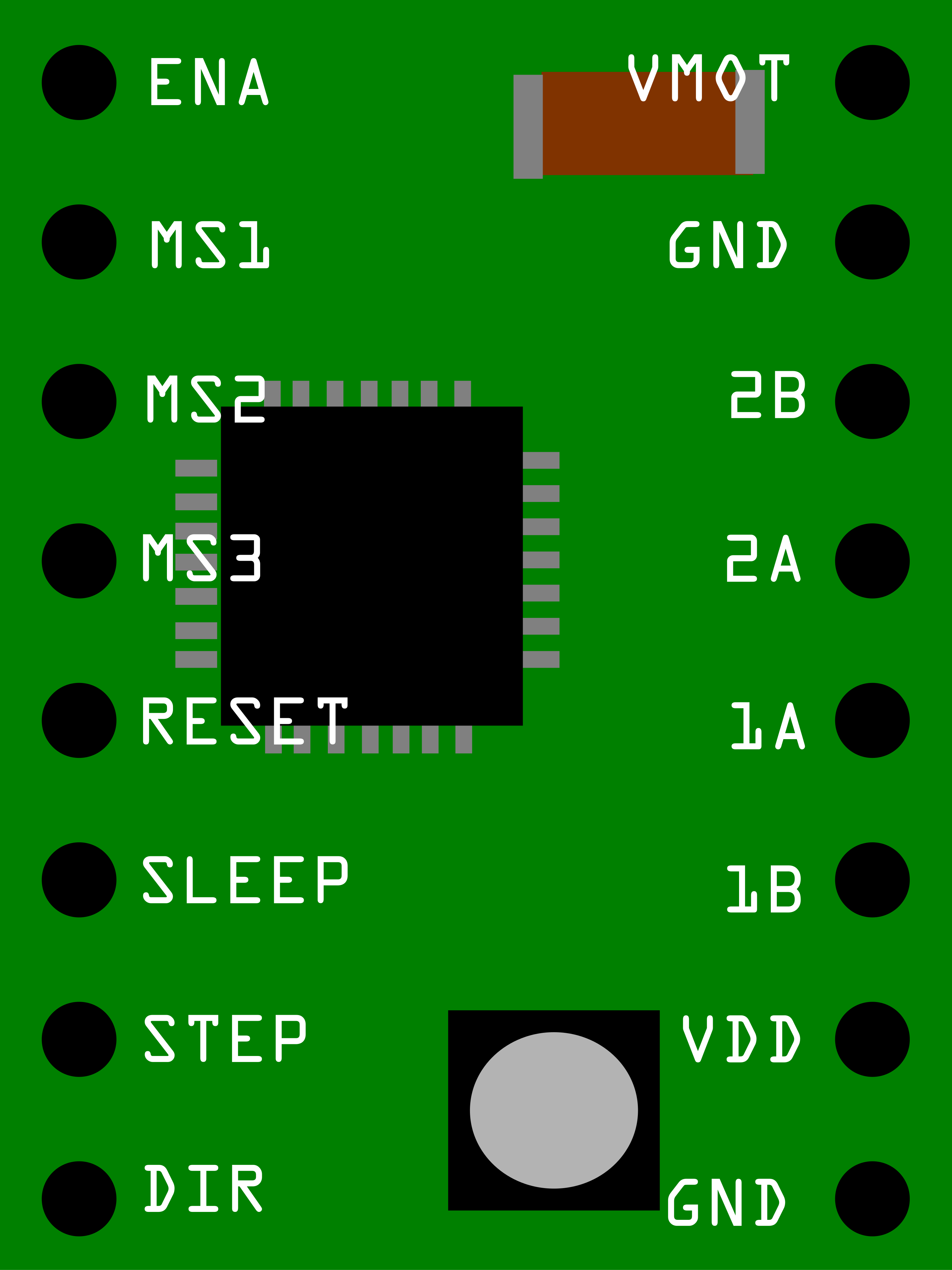
Pin Configuration and Descriptions

Pin Number Name Description
1 VMOT Motor supply voltage (8-35 V)
2 GND Ground (0 V)
3 2B Motor coil 2
4 2A Motor coil 2
5 1A Motor coil 1
6 1B Motor coil 1
7 VDD Logic supply voltage (3-5.5 V)
8 GND Ground (0 V) for logic
9 STEP Step input (pulses)
10 DIR Direction input
11 MS1 Microstep selection 1
12 MS2 Microstep selection 2
13 MS3 Microstep selection 3
14 RESET Resets the driver
15 SLEEP Sleep mode enable
16 FAULT Fault output (active low)
17 ENABLE Enables the FET outputs

Usage Instructions

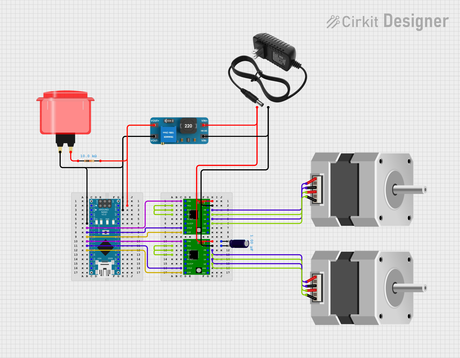
Connecting to a Circuit

  1. Connect the motor's coils to the A4988 outputs (1A, 1B, 2A, 2B).
  2. Apply the motor supply voltage (VMOT) and ground (GND) to the respective pins.
  3. Connect VDD to a 3-5.5 V logic supply and ground the logic ground (GND).
  4. Connect the STEP and DIR pins to the controlling microcontroller or another control circuit.
  5. Set the desired microstepping resolution using the MS1, MS2, and MS3 pins.
  6. Optionally, connect the SLEEP, RESET, and ENABLE pins as required by your application.

Important Considerations and Best Practices

  • Always ensure that the power supply matches the requirements of the motor and does not exceed the maximum voltage rating of the A4988.
  • Use decoupling capacitors close to the board to minimize voltage spikes.
  • Avoid disconnecting the motor while the driver is powered to prevent damage.
  • Heat sinking is recommended when running the driver close to its maximum current rating.
  • Microstepping resolution is set by the logic levels on MS1, MS2, and MS3. For example, driving all three pins low will set the driver to full step mode.

Example Code for Arduino UNO

// Define step and direction pins
#define DIR_PIN 2
#define STEP_PIN 3

void setup() {
  pinMode(DIR_PIN, OUTPUT);
  pinMode(STEP_PIN, OUTPUT);
}

void loop() {
  digitalWrite(DIR_PIN, HIGH); // Set the direction
  digitalWrite(STEP_PIN, HIGH); // Take one step
  delay(1);
  digitalWrite(STEP_PIN, LOW); // Complete the step
  delay(1);
  // Add more steps as needed
}

Troubleshooting and FAQs

Common Issues

  • Motor not moving: Check connections, ensure power supply is adequate, and verify that the STEP and DIR pins are being driven correctly.
  • Overheating: Ensure proper cooling, check current limiting settings, and verify that the motor specifications match the driver's capabilities.
  • Inconsistent movement: Check for mechanical obstructions, verify microstep settings, and ensure that the step pulse timing meets the motor's requirements.

Solutions and Tips for Troubleshooting

  • Double-check wiring, especially the motor coil connections and power supply.
  • Use a multimeter to verify the voltage at VMOT and VDD.
  • Ensure that the current limit is set correctly according to the motor's specifications.
  • If the driver enters a fault state, check for short circuits or over-temperature conditions.

FAQs

Q: How do I set the current limit on the A4988? A: The current limit is set via the onboard potentiometer. Turn it while measuring the voltage on the REF pin or monitoring the motor current directly.

Q: Can I drive two motors with one A4988 driver? A: No, the A4988 is designed to drive one bipolar stepper motor. Driving two motors requires two separate drivers.

Q: What is the purpose of the SLEEP pin? A: The SLEEP pin puts the driver into a low-power sleep mode when pulled low, which can be useful for power-saving when the motor is not in use.

Q: How do I know if the driver is in a fault state? A: The FAULT pin will be driven low if there is a fault condition. This can be monitored with a microcontroller or an LED indicator.

This documentation provides a comprehensive guide to using the A4988 Stepper Motor Driver Carrier. For further details, consult the manufacturer's datasheet and resources.