How to Use Relay 4 Channel 5v: Examples, Pinouts, and Specs
Introduction
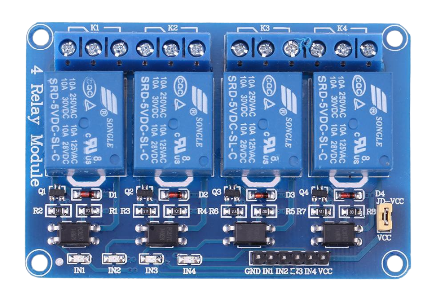
A Relay 4 Channel 5V module is an electronic device that allows a low-power signal to control up to four high-power circuits. It uses electromagnetic coils to open or close the circuits, effectively acting as a switch. This module is particularly useful when you need to control multiple AC/DC loads with digital signals from microcontrollers like Arduino.
Explore Projects Built with Relay 4 Channel 5v


Explore Projects Built with Relay 4 Channel 5v
Common Applications and Use Cases
- Home automation systems
- Industrial controls
- Automotive electronics
- Robotics
Technical Specifications
Key Technical Details
- Operating Voltage: 5V DC
- Trigger Voltage: 0-1.5V (LOW trigger), 2.5-5V (HIGH trigger)
- Switching Voltage: Up to 250V AC or 30V DC
- Switching Current: Up to 10A per channel
- Isolation: Opto-isolated inputs
Pin Configuration and Descriptions
| Pin Number | Description | Type |
|---|---|---|
| IN1 | Input signal 1 | Digital |
| IN2 | Input signal 2 | Digital |
| IN3 | Input signal 3 | Digital |
| IN4 | Input signal 4 | Digital |
| GND | Ground | Power |
| VCC | 5V Power Supply | Power |
| JD-VCC | Relay Power Supply | Power |
| NO1-NO4 | Normally Open Contact | Output |
| COM1-COM4 | Common Contact | Output |
| NC1-NC4 | Normally Closed Contact | Output |
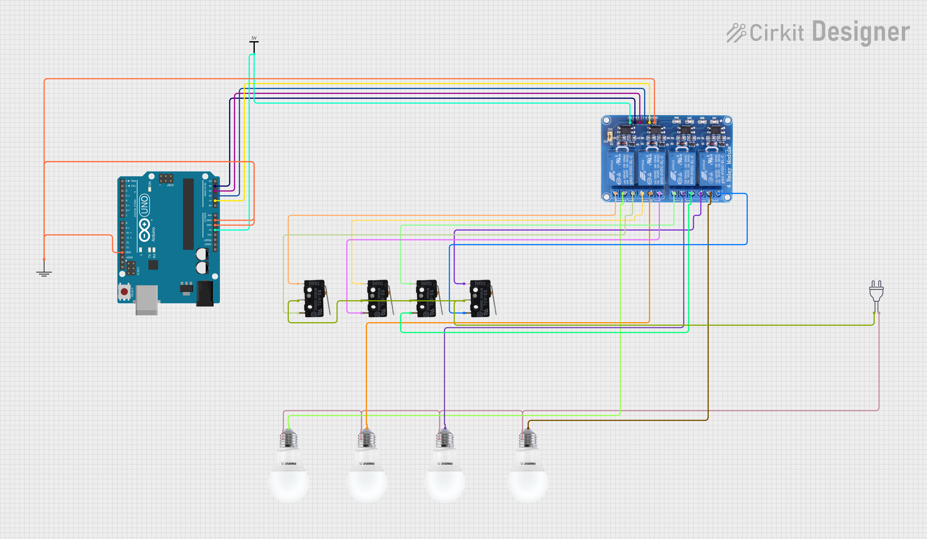
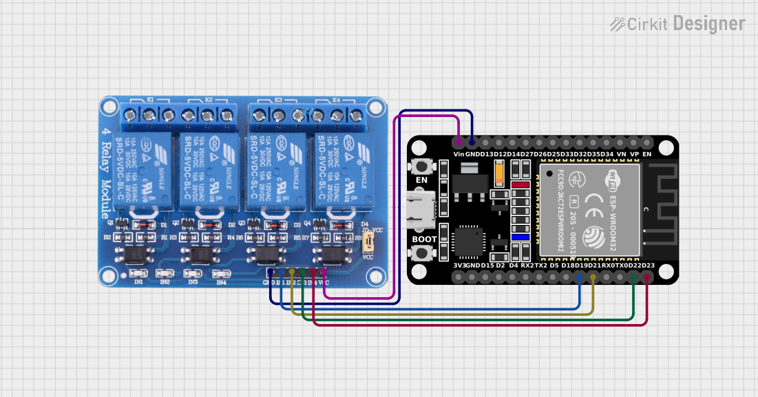
Usage Instructions
How to Use the Component in a Circuit
- Connect the VCC pin to the 5V power supply on your microcontroller.
- Connect the GND pin to the ground on your microcontroller.
- Connect the IN1-IN4 pins to the digital output pins on your microcontroller.
- Connect the JD-VCC pin to an external power supply if required.
- Connect the load to the NO/NC and COM pins of the relay.
Important Considerations and Best Practices
- Ensure that the power supply to JD-VCC is adequate for the loads being switched.
- Do not exceed the maximum switching voltage and current ratings.
- Use flyback diodes across inductive loads to prevent back EMF damage.
- Keep the control signal wires short to minimize interference.
Example Code for Arduino UNO
// Define relay control pins
const int relayPins[] = {2, 3, 4, 5};

void setup() {
  // Initialize all relay pins as outputs
  for (int i = 0; i < 4; i++) {
    pinMode(relayPins[i], OUTPUT);
    digitalWrite(relayPins[i], HIGH); // Start with all relays off
  }
}

void loop() {
  // Example: Turn on each relay for 2 seconds sequentially
  for (int i = 0; i < 4; i++) {
    digitalWrite(relayPins[i], LOW); // Turn on relay
    delay(2000);                      // Wait for 2 seconds
    digitalWrite(relayPins[i], HIGH); // Turn off relay
  }
}
Troubleshooting and FAQs
Common Issues Users Might Face
- Relay not activating: Check the input signal voltage and connections.
- Intermittent operation: Ensure that there is no loose wiring and that the power supply is stable.
- Clicking sound but no action: Verify that the load is properly connected and within the rated specifications.
Solutions and Tips for Troubleshooting
- Always double-check wiring against the module's pinout.
- Use a multimeter to verify the presence of control voltage at the relay inputs.
- If using an external power supply for JD-VCC, ensure that the ground is common with the microcontroller.
FAQs
Q: Can I control the relay module with a 3.3V signal? A: While the module is designed for 5V logic, some 3.3V signals may be sufficient to trigger the relay. However, it is not guaranteed and a level shifter might be required.
Q: Do I need to supply power to both VCC and JD-VCC? A: VCC is for the logic circuit, and JD-VCC is for the relay coils. For higher power applications, it is recommended to provide separate power to JD-VCC.
Q: Can I switch AC loads with this relay module? A: Yes, the relay module can switch both AC and DC loads, but ensure the load does not exceed the rated voltage and current.
Remember to always follow safety precautions when working with high voltage or current to prevent injury or damage to equipment.