Cirkit Designer
Your all-in-one circuit design IDE
Home /
Component Documentation
How to Use Piezo Speaker: Examples, Pinouts, and Specs

 Design with Piezo Speaker in Cirkit Designer
Introduction
A Piezo Speaker is an electronic device that produces sound by converting electrical signals into mechanical vibrations using piezoelectric materials. These speakers are widely used in various applications due to their small size, low power consumption, and ability to produce a wide range of frequencies. Common applications include:
- Alarms and buzzers
- Keypad feedback
- Sound effects in toys and gadgets
- Notification sounds in electronic devices
Explore Projects Built with Piezo Speaker
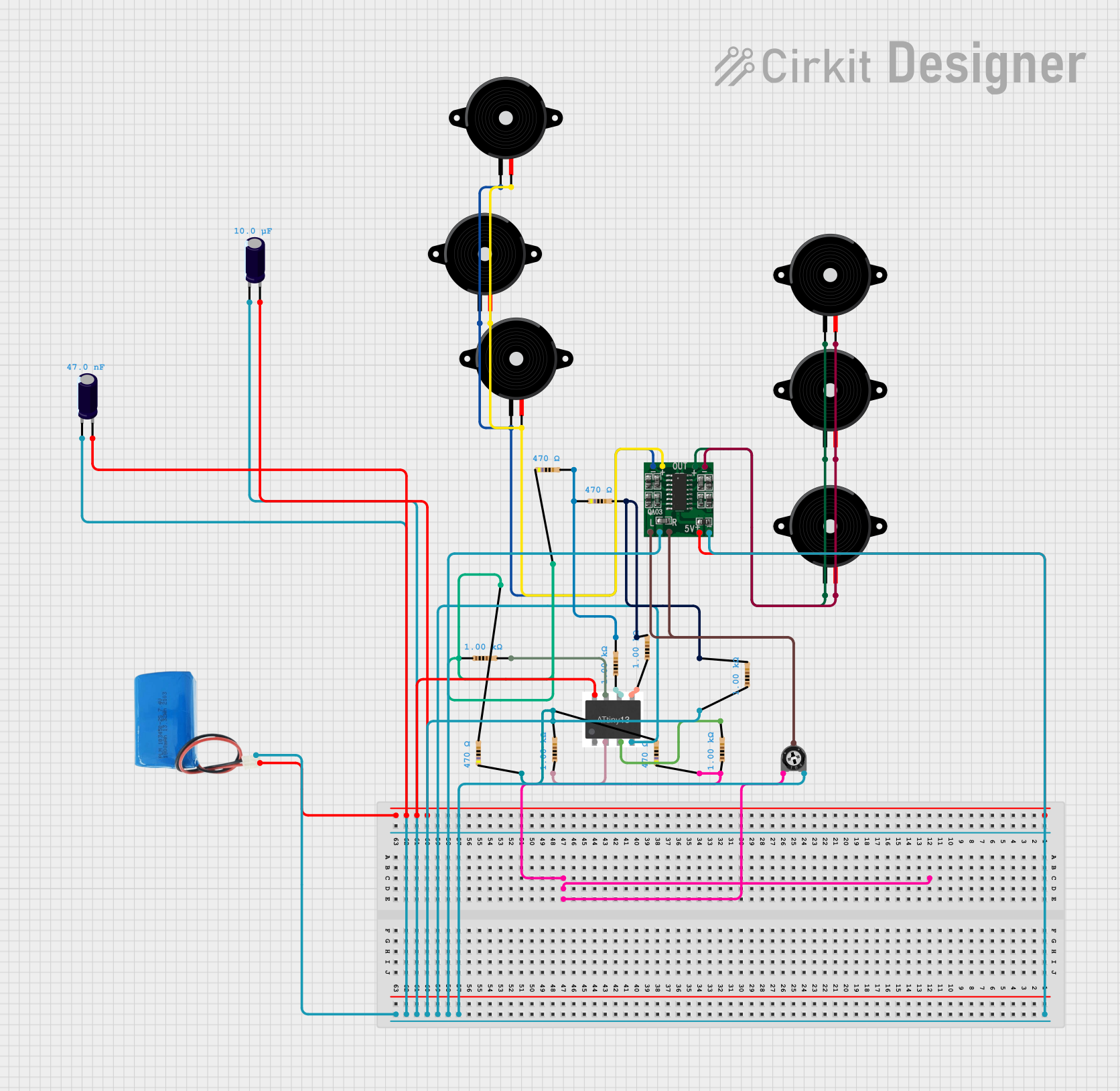
PAM8403 Amplified Piezo Speaker Array with ATTiny Control

This circuit is an audio amplification system with multiple piezo speakers driven by a PAM8403 amplifier IC. It features an ATtiny microcontroller for potential audio control, powered by a 5V battery with capacitors for stabilization and a trimmer potentiometer for input level adjustment.
 Open Project in Cirkit Designer
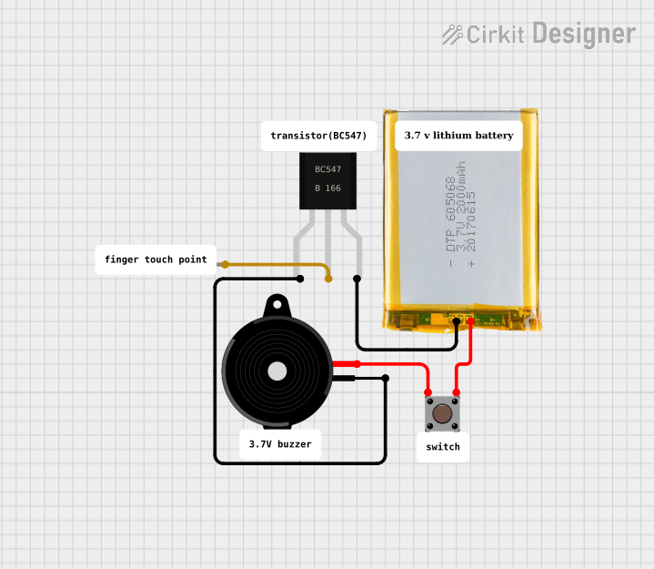
Battery-Powered Piezo Buzzer with Pushbutton Activation

This circuit appears to be a simple sound generation system controlled by a pushbutton. When the button is pressed, the battery powers the Piezo Speaker through a BC547 transistor, which likely acts as a switch to drive the speaker. A diode is connected to the base of the transistor, possibly for protection against reverse currents or to shape the input signal to the base.
 Open Project in Cirkit Designer
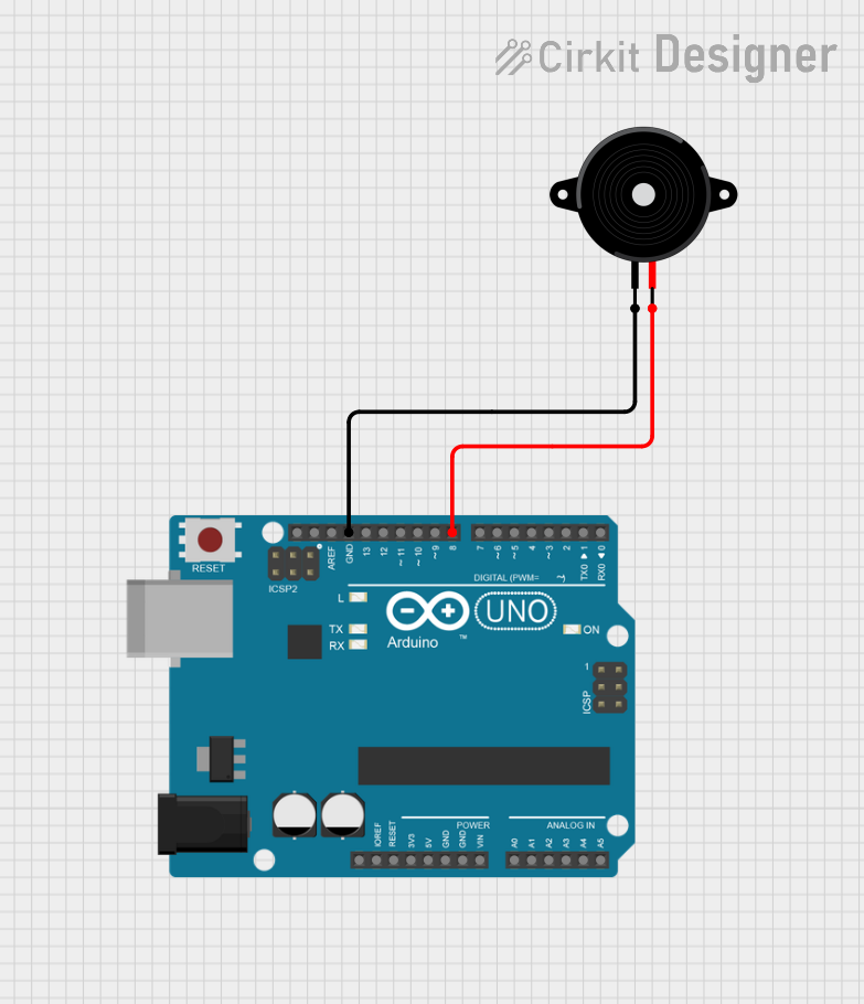
Arduino UNO Melody Player with Piezo Speaker

This circuit consists of an Arduino UNO microcontroller connected to a piezo speaker. The Arduino is programmed to play a predefined melody through the speaker upon startup, using digital pin 8 for the speaker signal and GND for the return path. The melody and its timing are defined in the embedded code, which utilizes an array of note frequencies and durations.
 Open Project in Cirkit Designer
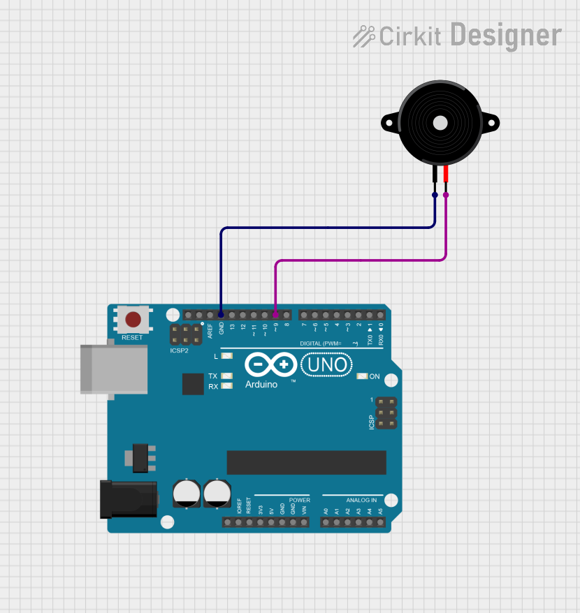
Arduino UNO Melody Player with Piezo Speaker

This circuit consists of an Arduino UNO microcontroller connected to a piezo speaker. The Arduino runs a program that plays a melody through the piezo speaker by generating specific frequencies on pin D9, with the speaker's other pin connected to ground.
 Open Project in Cirkit Designer
Explore Projects Built with Piezo Speaker

PAM8403 Amplified Piezo Speaker Array with ATTiny Control
This circuit is an audio amplification system with multiple piezo speakers driven by a PAM8403 amplifier IC. It features an ATtiny microcontroller for potential audio control, powered by a 5V battery with capacitors for stabilization and a trimmer potentiometer for input level adjustment.
 Open Project in Cirkit Designer
Battery-Powered Piezo Buzzer with Pushbutton Activation
This circuit appears to be a simple sound generation system controlled by a pushbutton. When the button is pressed, the battery powers the Piezo Speaker through a BC547 transistor, which likely acts as a switch to drive the speaker. A diode is connected to the base of the transistor, possibly for protection against reverse currents or to shape the input signal to the base.
 Open Project in Cirkit Designer
Arduino UNO Melody Player with Piezo Speaker
This circuit consists of an Arduino UNO microcontroller connected to a piezo speaker. The Arduino is programmed to play a predefined melody through the speaker upon startup, using digital pin 8 for the speaker signal and GND for the return path. The melody and its timing are defined in the embedded code, which utilizes an array of note frequencies and durations.
 Open Project in Cirkit Designer
Arduino UNO Melody Player with Piezo Speaker
This circuit consists of an Arduino UNO microcontroller connected to a piezo speaker. The Arduino runs a program that plays a melody through the piezo speaker by generating specific frequencies on pin D9, with the speaker's other pin connected to ground.
 Open Project in Cirkit Designer
Technical Specifications
Key Technical Details
| Parameter | Value |
|---|---|
| Operating Voltage | 3V to 12V |
| Current Consumption | 5mA to 30mA |
| Resonant Frequency | 2kHz to 4kHz |
| Sound Pressure Level | 85dB to 100dB at 10cm |
| Operating Temperature | -20°C to +70°C |
| Dimensions | Varies (commonly 10mm to 50mm) |
Pin Configuration and Descriptions
| Pin Number | Pin Name | Description |
|---|---|---|
| 1 | VCC | Positive voltage supply (3V to 12V) |
| 2 | GND | Ground |
Usage Instructions
How to Use the Component in a Circuit
- Power Supply: Connect the VCC pin of the Piezo Speaker to a positive voltage supply (3V to 12V).
- Ground Connection: Connect the GND pin to the ground of the circuit.
- Signal Input: To produce sound, apply a square wave signal to the VCC pin. The frequency of the square wave determines the pitch of the sound.
Example Circuit with Arduino UNO
// Example code to generate a tone using a Piezo Speaker connected to an Arduino UNO

const int piezoPin = 8; // Pin connected to the Piezo Speaker

void setup() {
  pinMode(piezoPin, OUTPUT); // Set the piezoPin as an output
}

void loop() {
  tone(piezoPin, 1000); // Generate a 1kHz tone
  delay(1000); // Wait for 1 second
  noTone(piezoPin); // Stop the tone
  delay(1000); // Wait for 1 second
}
Important Considerations and Best Practices
- Voltage Levels: Ensure the voltage supplied to the Piezo Speaker is within the specified range (3V to 12V) to avoid damage.
- Frequency Range: Operate the Piezo Speaker within its resonant frequency range (2kHz to 4kHz) for optimal sound output.
- Mounting: Securely mount the Piezo Speaker to prevent mechanical vibrations from affecting other components in the circuit.
Troubleshooting and FAQs
Common Issues Users Might Face
No Sound Output:
- Solution: Check the power supply connections and ensure the voltage is within the specified range. Verify that the signal input is correctly applied to the VCC pin.
Distorted Sound:
- Solution: Ensure the frequency of the input signal is within the resonant frequency range of the Piezo Speaker. Check for any loose connections or mechanical vibrations affecting the speaker.
Intermittent Sound:
- Solution: Verify the stability of the power supply and ensure there are no loose connections. Check the signal input for consistency.
FAQs
Q1: Can I use a Piezo Speaker with a microcontroller other than Arduino?
- A1: Yes, Piezo Speakers can be used with various microcontrollers. Ensure the microcontroller can generate the required square wave signal and provide the necessary voltage.
Q2: How can I increase the volume of the Piezo Speaker?
- A2: To increase the volume, you can increase the voltage supplied to the Piezo Speaker, but ensure it does not exceed the maximum specified voltage. Additionally, you can use an amplifier circuit to boost the signal.
Q3: Can I use a Piezo Speaker to play music?
- A3: While Piezo Speakers are primarily designed for simple tones and beeps, they can be used to play simple melodies. However, they are not suitable for high-fidelity music playback.
By following this documentation, users can effectively integrate and troubleshoot Piezo Speakers in their electronic projects.