How to Use TCA9548A I2C 8 CHANNEL Multiple extensions Develop: Examples, Pinouts, and Specs
Introduction
The TCA9548A is an I2C multiplexer designed to expand the number of I2C devices that can be connected to a single I2C bus. It features 8 independent channels, allowing the user to select one channel at a time to communicate with various I2C devices. This component is particularly useful in applications where multiple devices with the same I2C address need to coexist on the same bus.
Explore Projects Built with TCA9548A I2C 8 CHANNEL Multiple extensions Develop

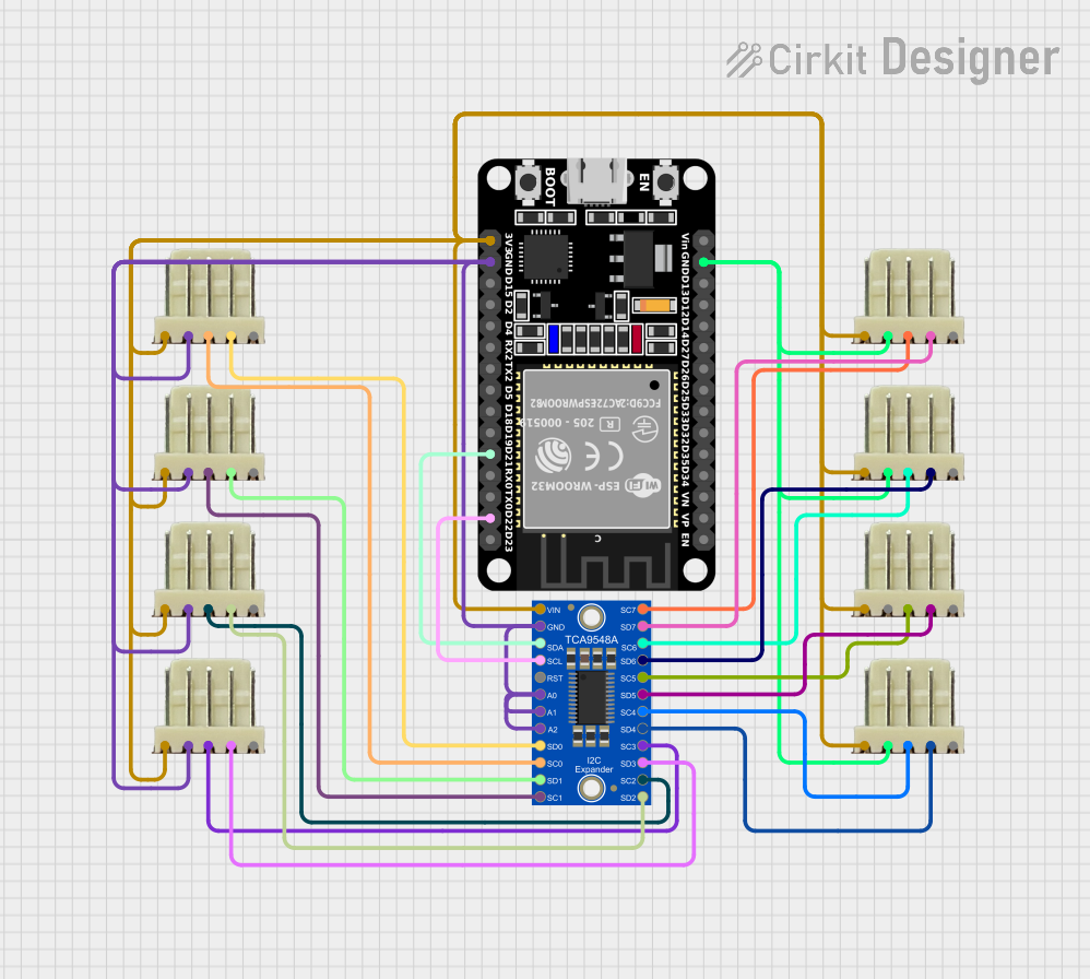
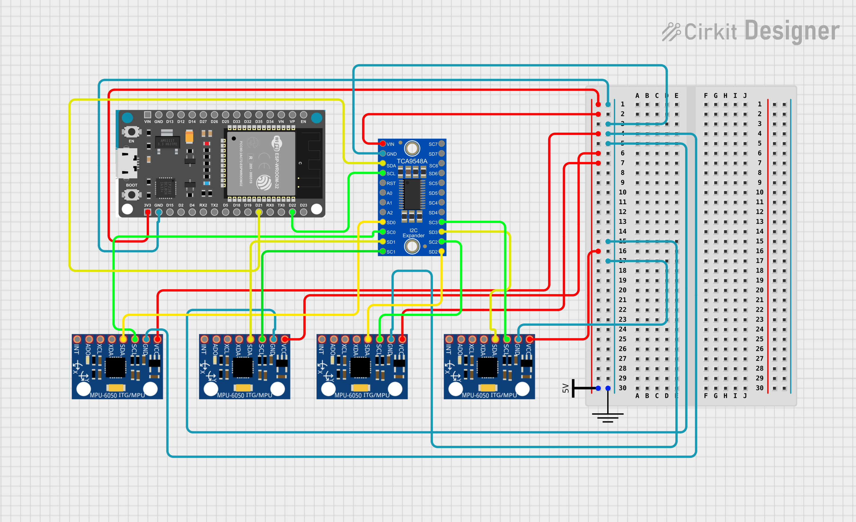
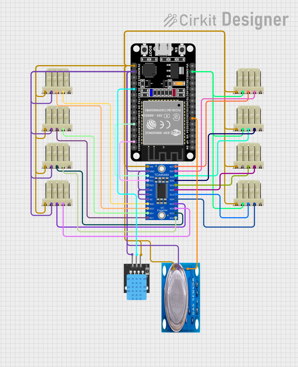
Explore Projects Built with TCA9548A I2C 8 CHANNEL Multiple extensions Develop
Common Applications and Use Cases
- Expanding the number of I2C devices connected to a microcontroller.
- Managing multiple I2C devices with identical addresses.
- Applications in sensor arrays, data acquisition systems, and IoT devices.
- Prototyping and development of complex I2C-based systems.
Technical Specifications
Key Technical Details
- Operating Voltage: 1.65V to 5.5V
- I2C Address Range: Configurable via A0, A1, and A2 pins (0x70 to 0x77)
- Maximum Clock Frequency: 400 kHz (I2C Fast Mode)
- Number of Channels: 8
- Channel Selection: Controlled via I2C commands
- Low Standby Current: 1 µA (typical)
- ESD Protection: ±4 kV Human Body Model (HBM)
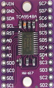
Pin Configuration and Descriptions
The TCA9548A is typically available in a 16-pin package. Below is the pinout and description:
| Pin | Name | Description |
|---|---|---|
| 1 | A0 | Address selection bit 0 (used to configure the I2C address). |
| 2 | A1 | Address selection bit 1 (used to configure the I2C address). |
| 3 | A2 | Address selection bit 2 (used to configure the I2C address). |
| 4 | VCC | Power supply input (1.65V to 5.5V). |
| 5 | SDA | I2C data line (connect to microcontroller's SDA pin). |
| 6 | SCL | I2C clock line (connect to microcontroller's SCL pin). |
| 7 | RESET | Active-low reset pin (optional, can be tied to VCC if not used). |
| 8-15 | SD0-SD7 | I2C data lines for channels 0 to 7 (connect to I2C devices). |
| 16 | GND | Ground connection. |
Usage Instructions
How to Use the TCA9548A in a Circuit
- Power the TCA9548A: Connect the VCC pin to a power source (1.65V to 5.5V) and the GND pin to ground.
- Configure the I2C Address: Use the A0, A1, and A2 pins to set the I2C address. These pins can be tied to GND (logic 0) or VCC (logic 1) to select an address between 0x70 and 0x77.
- Connect the I2C Bus: Attach the SDA and SCL pins to the corresponding pins on your microcontroller.
- Connect I2C Devices: Attach the SDA and SCL lines of your I2C devices to the appropriate channel pins (SD0-SD7).
- Control the Channels: Use I2C commands to select the desired channel for communication. Only one channel can be active at a time.
Important Considerations and Best Practices
- Pull-Up Resistors: Ensure that appropriate pull-up resistors (typically 4.7kΩ) are present on the SDA and SCL lines of the main I2C bus.
- Channel Isolation: Only one channel can be active at a time. Activating multiple channels simultaneously may cause communication errors.
- Reset Pin: If the RESET pin is not used, tie it to VCC to prevent accidental resets.
- Voltage Compatibility: Ensure that the voltage levels of the I2C devices connected to the channels match the operating voltage of the TCA9548A.
Example Code for Arduino UNO
Below is an example of how to use the TCA9548A with an Arduino UNO to communicate with a device on channel 0:
#include <Wire.h>

#define TCA9548A_ADDRESS 0x70 // Default I2C address of the TCA9548A

void selectChannel(uint8_t channel) {
  if (channel > 7) return; // Ensure the channel is valid (0-7)
  Wire.beginTransmission(TCA9548A_ADDRESS);
  Wire.write(1 << channel); // Select the desired channel
  Wire.endTransmission();
}

void setup() {
  Wire.begin(); // Initialize I2C communication
  Serial.begin(9600); // Initialize serial communication for debugging

  // Select channel 0
  selectChannel(0);
  Serial.println("Channel 0 selected");
}

void loop() {
  // Example: Communicate with an I2C device on channel 0
  Wire.beginTransmission(0x40); // Replace 0x40 with the I2C address of your device
  Wire.write(0x00); // Example command
  Wire.endTransmission();

  delay(1000); // Wait for 1 second
}
Troubleshooting and FAQs
Common Issues and Solutions
No Communication with I2C Devices:
- Cause: Incorrect I2C address or channel not selected.
- Solution: Verify the TCA9548A's I2C address and ensure the correct channel is selected using I2C commands.
Multiple Devices Not Working:
- Cause: Pull-up resistors missing or incorrect.
- Solution: Ensure proper pull-up resistors are present on the main I2C bus.
Device Not Responding After Reset:
- Cause: RESET pin not properly configured.
- Solution: Tie the RESET pin to VCC if not used, or ensure it is pulled high during operation.
Communication Errors at High Speeds:
- Cause: Exceeding the maximum clock frequency.
- Solution: Ensure the I2C clock frequency does not exceed 400 kHz.
FAQs
Can I activate multiple channels simultaneously? No, the TCA9548A allows only one channel to be active at a time.
What happens if I don't configure the address pins (A0, A1, A2)? If left floating, the address pins may pick up noise, leading to unpredictable behavior. Always tie them to GND or VCC.
Is the TCA9548A compatible with 3.3V and 5V systems? Yes, the TCA9548A operates within a voltage range of 1.65V to 5.5V, making it compatible with both 3.3V and 5V systems.