How to Use RC-36 reed relay: Examples, Pinouts, and Specs
Introduction
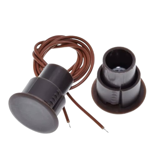
The RC-36 reed relay, manufactured by TZT, is an electromagnetic switch that uses a magnetic field to operate a pair of contacts. This component is designed for low-power applications, offering reliable isolation and control in electronic circuits. Its compact design and efficient operation make it ideal for use in signal switching, test equipment, telecommunications, and other low-power control systems.
Explore Projects Built with RC-36 reed relay
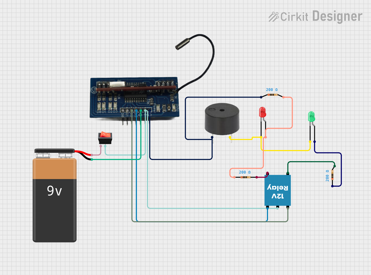
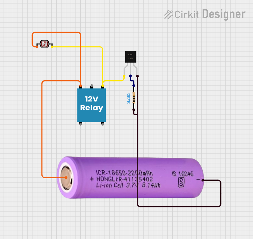
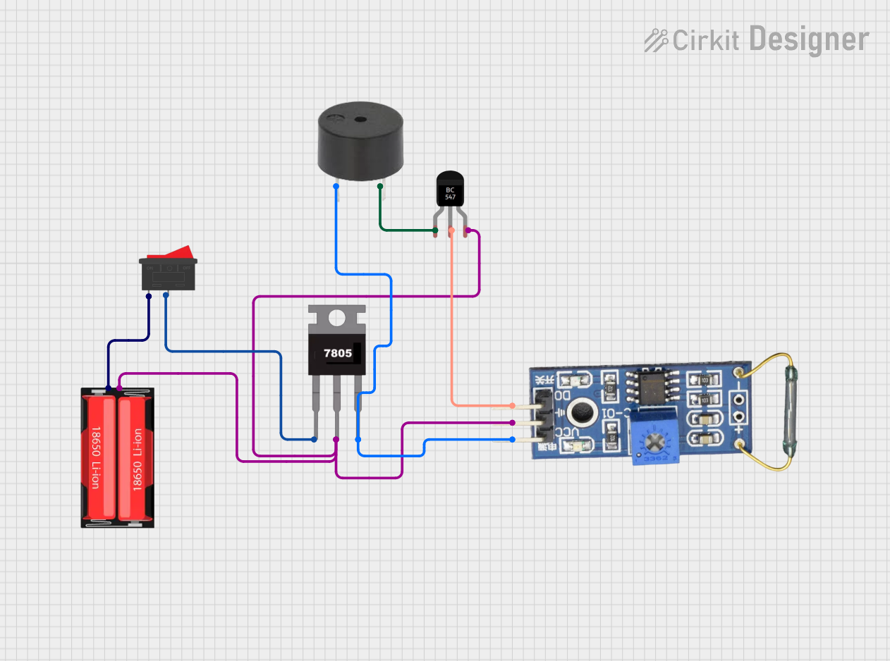
Explore Projects Built with RC-36 reed relay
Common Applications
- Signal switching in low-power circuits
- Isolation between control and load circuits
- Test and measurement equipment
- Telecommunications systems
- Industrial automation
Technical Specifications
The RC-36 reed relay is optimized for low-power applications and provides excellent performance in compact designs. Below are the key technical details:
Electrical Specifications
| Parameter | Value |
|---|---|
| Coil Voltage | 5V DC |
| Coil Resistance | 500 Ω ±10% |
| Contact Rating | 10W (Max) |
| Switching Voltage | 200V DC (Max) |
| Switching Current | 0.5A (Max) |
| Breakdown Voltage | 250V DC |
| Operate Time | 0.5 ms (Typical) |
| Release Time | 0.1 ms (Typical) |
| Insulation Resistance | ≥10⁹ Ω |
Mechanical Specifications
| Parameter | Value |
|---|---|
| Dimensions | 20mm x 10mm x 8mm |
| Weight | 2g |
| Contact Material | Ruthenium |
| Operating Temperature | -40°C to +85°C |
| Storage Temperature | -55°C to +125°C |
Pin Configuration
The RC-36 reed relay has a 4-pin configuration. The table below describes each pin:
| Pin Number | Name | Description |
|---|---|---|
| 1 | Coil (+) | Positive terminal of the relay coil |
| 2 | Coil (-) | Negative terminal of the relay coil |
| 3 | Common (COM) | Common terminal of the relay contacts |
| 4 | Normally Open (NO) | Normally open contact terminal |
Usage Instructions
The RC-36 reed relay is straightforward to use in electronic circuits. Follow the steps below to integrate it into your design:
Circuit Connection
- Coil Connection: Connect the coil terminals (Pin 1 and Pin 2) to a DC voltage source. Ensure the voltage matches the rated coil voltage (5V DC).
- Contact Connection: Connect the load circuit to the Common (COM) terminal (Pin 3) and the Normally Open (NO) terminal (Pin 4). When the relay is activated, the NO terminal will close the circuit with the COM terminal.
- Control Signal: Use a transistor or microcontroller to control the relay coil. This ensures proper isolation and prevents overloading the control circuit.
Important Considerations
- Diode Protection: Always connect a flyback diode across the coil terminals to protect the circuit from voltage spikes when the relay is deactivated.
- Current Limiting: Ensure the load current does not exceed the relay's maximum switching current (0.5A).
- Mounting: Secure the relay on a PCB or breadboard to prevent mechanical stress on the pins.
Example: Connecting RC-36 to an Arduino UNO
Below is an example of how to control the RC-36 reed relay using an Arduino UNO:
Circuit Diagram
- Connect Pin 1 (Coil +) to a digital output pin on the Arduino through a 1kΩ resistor.
- Connect Pin 2 (Coil -) to the Arduino GND.
- Connect a flyback diode (e.g., 1N4007) across the coil terminals (Pin 1 and Pin 2).
- Connect the load circuit to Pin 3 (COM) and Pin 4 (NO).
Arduino Code
// RC-36 Reed Relay Control Example
// This code demonstrates how to control the RC-36 relay using an Arduino UNO.

const int relayPin = 7; // Define the digital pin connected to the relay coil

void setup() {
  pinMode(relayPin, OUTPUT); // Set the relay pin as an output
  digitalWrite(relayPin, LOW); // Ensure the relay is off at startup
}

void loop() {
  digitalWrite(relayPin, HIGH); // Activate the relay
  delay(1000); // Keep the relay on for 1 second
  digitalWrite(relayPin, LOW); // Deactivate the relay
  delay(1000); // Keep the relay off for 1 second
}
Best Practices
- Avoid exceeding the relay's voltage and current ratings to ensure long-term reliability.
- Use proper insulation and spacing to prevent short circuits or accidental contact.
- Test the relay in your circuit before deploying it in critical applications.
Troubleshooting and FAQs
Common Issues
Relay Not Activating
- Cause: Insufficient coil voltage or incorrect wiring.
- Solution: Verify the coil voltage is 5V DC and check the wiring connections.
Contact Not Closing
- Cause: Faulty relay or excessive load current.
- Solution: Test the relay with a multimeter and ensure the load current is within the rated limit.
Voltage Spikes Damaging Circuit
- Cause: Missing or improperly connected flyback diode.
- Solution: Install a flyback diode across the coil terminals with the correct polarity.
Relay Heating Up
- Cause: Overvoltage or prolonged activation.
- Solution: Ensure the coil voltage does not exceed 5V DC and use a duty cycle to limit activation time.
FAQs
Q1: Can the RC-36 relay switch AC loads?
A1: Yes, the RC-36 can switch low-power AC loads, but ensure the voltage and current ratings are not exceeded.
Q2: What is the lifespan of the RC-36 relay?
A2: The RC-36 has a mechanical lifespan of over 10 million operations under normal conditions.
Q3: Can I use the RC-36 with a 3.3V microcontroller?
A3: Yes, but you will need a transistor or MOSFET to drive the relay coil with 5V DC.
Q4: Is the RC-36 suitable for high-frequency switching?
A4: The RC-36 is not ideal for high-frequency switching due to its mechanical nature. Use a solid-state relay for such applications.