Cirkit Designer Logo
Cirkit Designer
Your all-in-one circuit design IDE
Home / 
Component Documentation

How to Use 05 Direction Navigation Button Module: Examples, Pinouts, and Specs

Image of 05 Direction Navigation Button Module
Cirkit Designer LogoDesign with 05 Direction Navigation Button Module in Cirkit Designer

Introduction

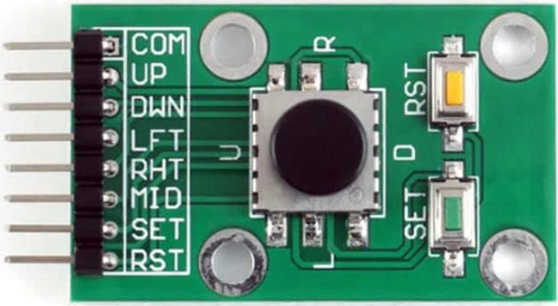
The 05 Direction Navigation Button Module is an interface component that provides five tactile buttons arranged in a cross formation, allowing for directional input and selection in electronic projects. This module is commonly used for menu navigation, game controllers, and as an input device for various microcontroller-based projects.

Explore Projects Built with 05 Direction Navigation Button Module

Use Cirkit Designer to design, explore, and prototype these projects online. Some projects support real-time simulation. Click "Open Project" to start designing instantly!
Arduino Nano-Based Portable GSM-GPS Navigator with Compass and Stepper Motor Control
Image of Compass: A project utilizing 05 Direction Navigation Button Module in a practical application
This circuit features an Arduino Nano microcontroller coordinating communication, navigation, and motion control functions. It includes modules for GSM, GPS, and digital compass capabilities, as well as a stepper motor for precise movement, all powered by a LiPo battery with voltage regulation.
Cirkit Designer LogoOpen Project in Cirkit Designer
Arduino Nano-Based Panic Button System with GPS and GSM Modules
Image of panic button .2\: A project utilizing 05 Direction Navigation Button Module in a practical application
This circuit is designed as a panic button system featuring an Arduino Nano interfaced with a NEO6MV2 GPS module and three SIM800L GSM modules. It includes four pushbuttons, each assigned to trigger a call to a specific emergency service (hospital, fire department, police) or to send the GPS location. The system is powered by a lithium battery with a charging module, and it can send the GPS location to a predefined number or alongside an emergency call when the corresponding buttons are pressed simultaneously.
Cirkit Designer LogoOpen Project in Cirkit Designer
Arduino Nano-Based GPS and GSM Alert System with Pushbutton Activation
Image of GPS Tracker: A project utilizing 05 Direction Navigation Button Module in a practical application
This circuit is a GPS-enabled emergency alert system using an Arduino Nano, a SIM800L GSM module, and a Neo 6M GPS module. When either of the two pushbuttons is pressed, the system sends an SMS with the GPS location or makes a call to a predefined phone number, providing a means to request help in emergencies.
Cirkit Designer LogoOpen Project in Cirkit Designer
Arduino Nano GPS and GSM Tracker with Battery Charging Module
Image of JMTJMD: A project utilizing 05 Direction Navigation Button Module in a practical application
This circuit is a GPS and GSM-based tracking system powered by a TP4056 battery charging module. It uses an Arduino Nano to interface with a GPS NEO 6M module for location data and a Sim800l module for GSM communication. A pushbutton and resistor are included for user input, and the system is powered by a rechargeable battery.
Cirkit Designer LogoOpen Project in Cirkit Designer

Explore Projects Built with 05 Direction Navigation Button Module

Use Cirkit Designer to design, explore, and prototype these projects online. Some projects support real-time simulation. Click "Open Project" to start designing instantly!
Image of Compass: A project utilizing 05 Direction Navigation Button Module in a practical application
Arduino Nano-Based Portable GSM-GPS Navigator with Compass and Stepper Motor Control
This circuit features an Arduino Nano microcontroller coordinating communication, navigation, and motion control functions. It includes modules for GSM, GPS, and digital compass capabilities, as well as a stepper motor for precise movement, all powered by a LiPo battery with voltage regulation.
Cirkit Designer LogoOpen Project in Cirkit Designer
Image of panic button .2\: A project utilizing 05 Direction Navigation Button Module in a practical application
Arduino Nano-Based Panic Button System with GPS and GSM Modules
This circuit is designed as a panic button system featuring an Arduino Nano interfaced with a NEO6MV2 GPS module and three SIM800L GSM modules. It includes four pushbuttons, each assigned to trigger a call to a specific emergency service (hospital, fire department, police) or to send the GPS location. The system is powered by a lithium battery with a charging module, and it can send the GPS location to a predefined number or alongside an emergency call when the corresponding buttons are pressed simultaneously.
Cirkit Designer LogoOpen Project in Cirkit Designer
Image of GPS Tracker: A project utilizing 05 Direction Navigation Button Module in a practical application
Arduino Nano-Based GPS and GSM Alert System with Pushbutton Activation
This circuit is a GPS-enabled emergency alert system using an Arduino Nano, a SIM800L GSM module, and a Neo 6M GPS module. When either of the two pushbuttons is pressed, the system sends an SMS with the GPS location or makes a call to a predefined phone number, providing a means to request help in emergencies.
Cirkit Designer LogoOpen Project in Cirkit Designer
Image of JMTJMD: A project utilizing 05 Direction Navigation Button Module in a practical application
Arduino Nano GPS and GSM Tracker with Battery Charging Module
This circuit is a GPS and GSM-based tracking system powered by a TP4056 battery charging module. It uses an Arduino Nano to interface with a GPS NEO 6M module for location data and a Sim800l module for GSM communication. A pushbutton and resistor are included for user input, and the system is powered by a rechargeable battery.
Cirkit Designer LogoOpen Project in Cirkit Designer

Common Applications and Use Cases

  • User interfaces for electronic devices
  • DIY game controllers
  • Menu navigation for LCD or OLED displays
  • Robotics control interfaces

Technical Specifications

Key Technical Details

  • Operating Voltage: Typically 3.3V to 5V
  • Output: Digital signal for each button
  • Interface: 5-pin (one for each direction and one common ground)
  • Current Rating: 10mA per button (typical)

Pin Configuration and Descriptions

Pin Number Description Notes
1 Up Button Output Active LOW when button pressed
2 Down Button Output Active LOW when button pressed
3 Left Button Output Active LOW when button pressed
4 Right Button Output Active LOW when button pressed
5 Center/Select Button Output Active LOW when button pressed
GND Ground Common ground for all buttons

Usage Instructions

How to Use the Component in a Circuit

  1. Connect the module's ground pin to the ground of your microcontroller.
  2. Connect each of the directional output pins to a digital input pin on your microcontroller.
  3. Ensure that the operating voltage of the module is compatible with your microcontroller's logic level.
  4. Use pull-up resistors (either internal or external) to ensure a stable HIGH signal when buttons are not pressed.

Important Considerations and Best Practices

  • Debounce the buttons either through software or with external hardware to prevent false triggering due to mechanical bounce.
  • Avoid applying force that exceeds the mechanical limits of the buttons to prevent damage.
  • Keep the voltage within specified limits to prevent damage to the module and the microcontroller.

Example Code for Arduino UNO

// Define the pin connections
const int upButtonPin = 2;
const int downButtonPin = 3;
const int leftButtonPin = 4;
const int rightButtonPin = 5;
const int selectButtonPin = 6;

void setup() {
  // Initialize the button pins as inputs with internal pull-up resistors
  pinMode(upButtonPin, INPUT_PULLUP);
  pinMode(downButtonPin, INPUT_PULLUP);
  pinMode(leftButtonPin, INPUT_PULLUP);
  pinMode(rightButtonPin, INPUT_PULLUP);
  pinMode(selectButtonPin, INPUT_PULLUP);
}

void loop() {
  // Read the state of each button
  bool upPressed = !digitalRead(upButtonPin);
  bool downPressed = !digitalRead(downButtonPin);
  bool leftPressed = !digitalRead(leftButtonPin);
  bool rightPressed = !digitalRead(rightButtonPin);
  bool selectPressed = !digitalRead(selectButtonPin);

  // Implement logic based on button state
  // For example, print the button pressed to the Serial Monitor
  if (upPressed) {
    Serial.println("Up button pressed");
  }
  if (downPressed) {
    Serial.println("Down button pressed");
  }
  if (leftPressed) {
    Serial.println("Left button pressed");
  }
  if (rightPressed) {
    Serial.println("Right button pressed");
  }
  if (selectPressed) {
    Serial.println("Select button pressed");
  }

  // Add a small delay to debounce
  delay(50);
}

Troubleshooting and FAQs

Common Issues Users Might Face

  • Buttons not responding: Ensure all connections are secure and the pins are correctly configured in your code.
  • False triggers or bouncing: Implement software debouncing or add hardware debouncing circuits.
  • Inconsistent behavior across different power supplies: Verify that the power supply is within the operating voltage range and is stable.

Solutions and Tips for Troubleshooting

  • Double-check wiring against the pin configuration table.
  • Use the Serial.print function to debug button states in real-time.
  • If using an external pull-up resistor, ensure it is of an appropriate value (typically 10kΩ).

FAQs

Q: Can I use this module with a 3.3V system? A: Yes, the module typically operates between 3.3V and 5V.

Q: How can I prevent the buttons from bouncing? A: Implement a debounce algorithm in your code or use a hardware debounce circuit with a capacitor and resistor.

Q: Is it possible to use this module with a Raspberry Pi? A: Yes, as long as the GPIO pins are configured correctly and you take into account the Raspberry Pi's 3.3V logic level.