
How to Use STM32F103C8T6: Examples, Pinouts, and Specs
 Design with STM32F103C8T6 in Cirkit Designer
Introduction
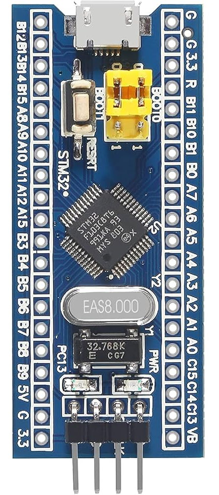
The STM32F103C8T6, commonly referred to as the "Blue Pill," is a 32-bit microcontroller developed by STMicroelectronics. It is based on the ARM Cortex-M3 core and is designed for high-performance, low-power embedded applications. With 64KB of flash memory, 20KB of SRAM, and a wide range of peripherals, the Blue Pill is a versatile and cost-effective solution for hobbyists and professionals alike.
Explore Projects Built with STM32F103C8T6
 Open Project in Cirkit Designer
 Open Project in Cirkit Designer
 Open Project in Cirkit Designer
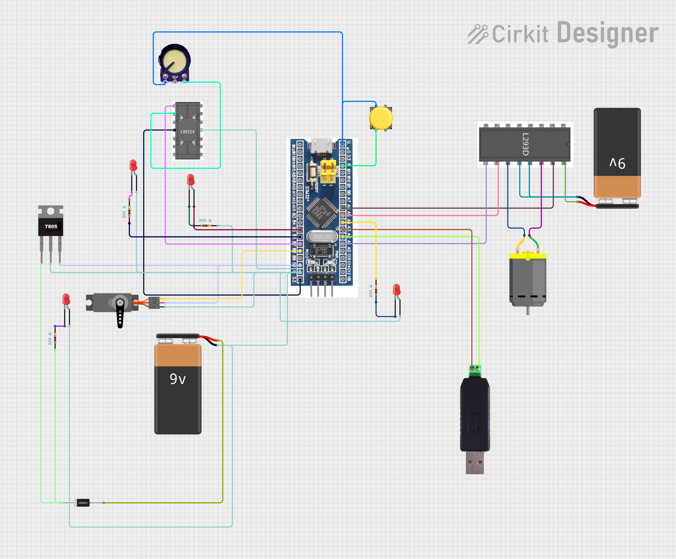 Open Project in Cirkit Designer
Explore Projects Built with STM32F103C8T6
Open Project in Cirkit DesignerOpen Project in Cirkit DesignerOpen Project in Cirkit DesignerOpen Project in Cirkit DesignerCommon Applications and Use Cases
- Embedded systems and IoT devices
- Robotics and motor control
- Data acquisition and signal processing
- Prototyping and educational projects
- Communication interfaces (e.g., UART, SPI, I2C, CAN)
Technical Specifications
Key Technical Details
| Parameter | Value |
|---|---|
| Core | ARM Cortex-M3 |
| Operating Frequency | 72 MHz |
| Flash Memory | 64 KB |
| SRAM | 20 KB |
| Operating Voltage | 2.0V to 3.6V |
| GPIO Pins | 37 |
| Communication Interfaces | UART, SPI, I2C, CAN, USB |
| ADC Resolution | 12-bit (up to 16 channels) |
| Timers | 3 general-purpose, 1 advanced |
| Power Consumption | ~36 mA at 72 MHz (typical) |
| Package | LQFP48 |
Pin Configuration and Descriptions
The STM32F103C8T6 features 48 pins, with 37 GPIO pins that can be configured for various functions. Below is a summary of key pins:
| Pin Name | Pin Number | Function(s) | Description |
|---|---|---|---|
| VDD | 2, 31 | Power Supply | 3.3V power input |
| VSS | 8, 23 | Ground | Ground connection |
| PA0-PA15 | Multiple | GPIO, ADC, Timer, etc. | General-purpose I/O pins |
| PB0-PB15 | Multiple | GPIO, ADC, Timer, etc. | General-purpose I/O pins |
| PC13-PC15 | Multiple | GPIO | General-purpose I/O pins |
| NRST | 7 | Reset | Active-low reset pin |
| BOOT0 | 44 | Boot Mode Selection | Selects boot mode (Flash/Bootloader) |
| USB_DM | 11 | USB Data- | USB data line (negative) |
| USB_DP | 12 | USB Data+ | USB data line (positive) |
For a complete pinout, refer to the STM32F103C8T6 datasheet.
Usage Instructions
How to Use the STM32F103C8T6 in a Circuit
- Power Supply: Provide a stable 3.3V power supply to the VDD pins and connect the VSS pins to ground.
- Boot Mode Selection: Use the BOOT0 pin to select the boot mode:
- Connect BOOT0 to GND for normal Flash memory operation.
- Connect BOOT0 to 3.3V for bootloader mode (e.g., for firmware upload via USB).
- Programming: Use an ST-Link programmer or USB-to-serial adapter to upload code. The microcontroller supports SWD (Serial Wire Debug) for debugging and programming.
- Peripherals: Configure GPIO pins and peripherals (e.g., UART, SPI, I2C) as needed in your firmware.
Important Considerations and Best Practices
- Voltage Levels: Ensure all input signals are within the 3.3V range to avoid damaging the microcontroller.
- Decoupling Capacitors: Place 0.1 µF decoupling capacitors close to the VDD pins to stabilize the power supply.
- Clock Source: The Blue Pill includes an 8 MHz crystal oscillator for the system clock. Ensure proper configuration in your firmware.
- Pull-Up/Down Resistors: Use pull-up or pull-down resistors for unused pins to prevent floating states.
Example Code for Arduino IDE
The STM32F103C8T6 can be programmed using the Arduino IDE with the STM32duino core installed. Below is an example of blinking an LED connected to pin PC13:
// Blink an LED on PC13 (built-in LED on Blue Pill)

void setup() {
  pinMode(PC13, OUTPUT); // Set PC13 as an output pin
}

void loop() {
  digitalWrite(PC13, HIGH); // Turn the LED on
  delay(1000);              // Wait for 1 second
  digitalWrite(PC13, LOW);  // Turn the LED off
  delay(1000);              // Wait for 1 second
}
Note: Ensure the correct board and upload method are selected in the Arduino IDE.
Troubleshooting and FAQs
Common Issues and Solutions
Microcontroller Not Responding
- Cause: Incorrect BOOT0 pin configuration.
- Solution: Ensure BOOT0 is connected to GND for normal operation.
USB Not Recognized
- Cause: Missing or incorrect USB bootloader.
- Solution: Flash the STM32 USB bootloader using an ST-Link programmer.
Code Upload Fails
- Cause: Incorrect upload method or baud rate.
- Solution: Verify the upload settings in your IDE and ensure the correct COM port is selected.
GPIO Pins Not Working
- Cause: Pins not configured correctly in firmware.
- Solution: Double-check the pinMode and peripheral configurations in your code.
FAQs
Q: Can I power the Blue Pill with 5V?
- A: No, the STM32F103C8T6 operates at 3.3V. Use a voltage regulator if your power source is 5V.
Q: How do I reset the microcontroller?
- A: Press the onboard reset button or pull the NRST pin low.
Q: Can I use the Blue Pill with an external programmer?
- A: Yes, you can use an ST-Link or other SWD-compatible programmer for debugging and programming.
Q: Is the Blue Pill compatible with Arduino libraries?
- A: Many Arduino libraries are compatible when using the STM32duino core.
By following this documentation, you can effectively utilize the STM32F103C8T6 microcontroller in your projects.