How to Use ATGM336H: Examples, Pinouts, and Specs
Introduction
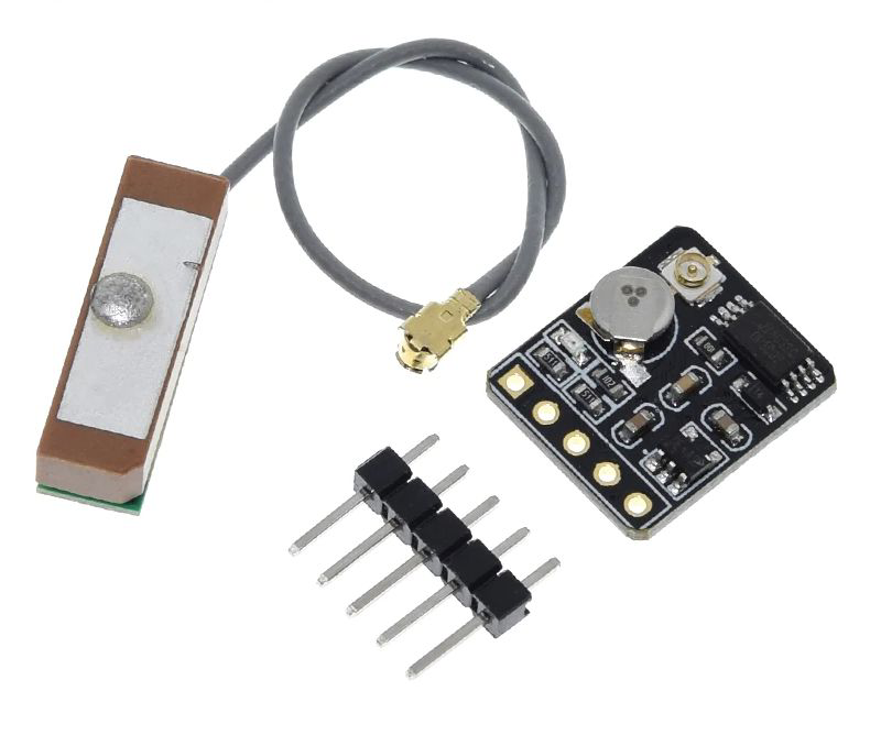
The ATGM336H is a high-precision Micro-Electro-Mechanical Systems (MEMS) capacitive tilt sensor module. It features an integrated low-noise signal conditioning amplifier and offers digital output via SPI/I2C communication protocols. This sensor is designed to measure the tilt angle of an object with respect to gravity, making it ideal for applications in fields such as robotics, automotive systems, platform stabilization, and more.
Explore Projects Built with ATGM336H
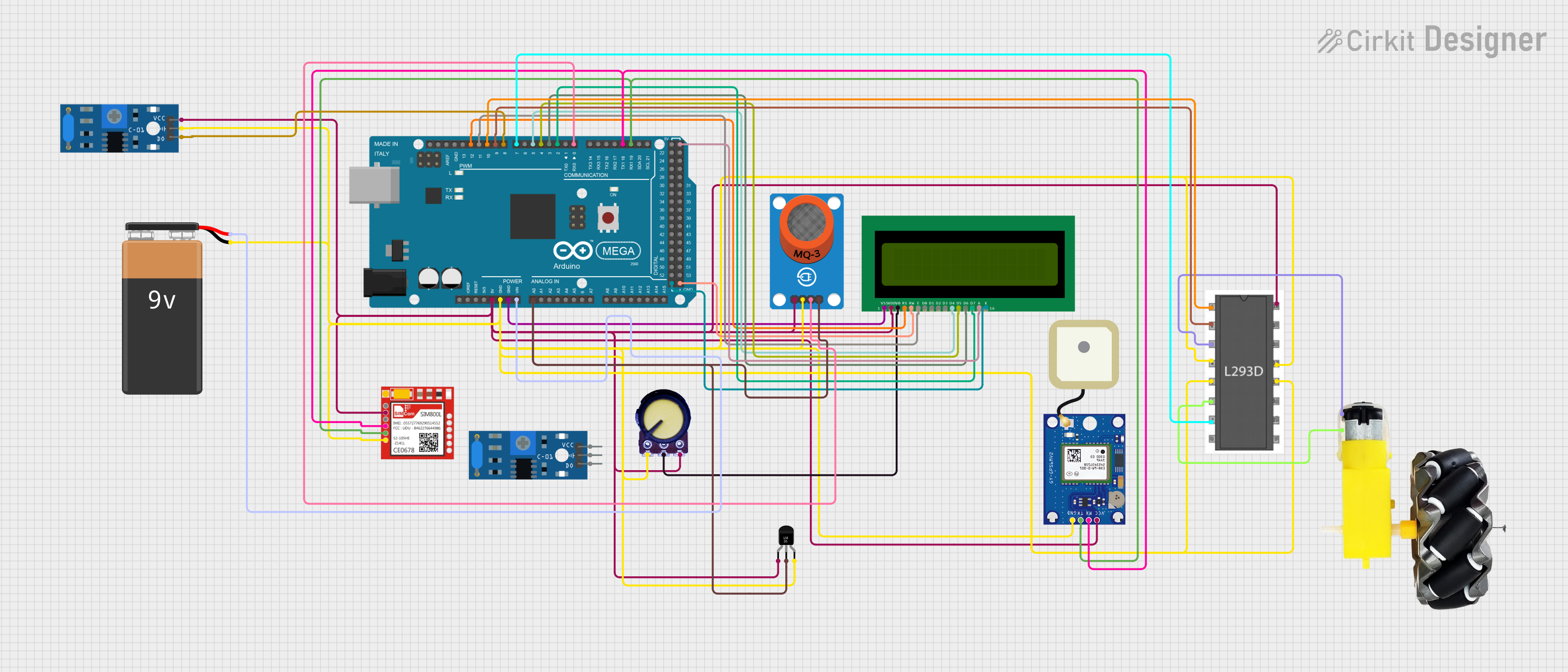
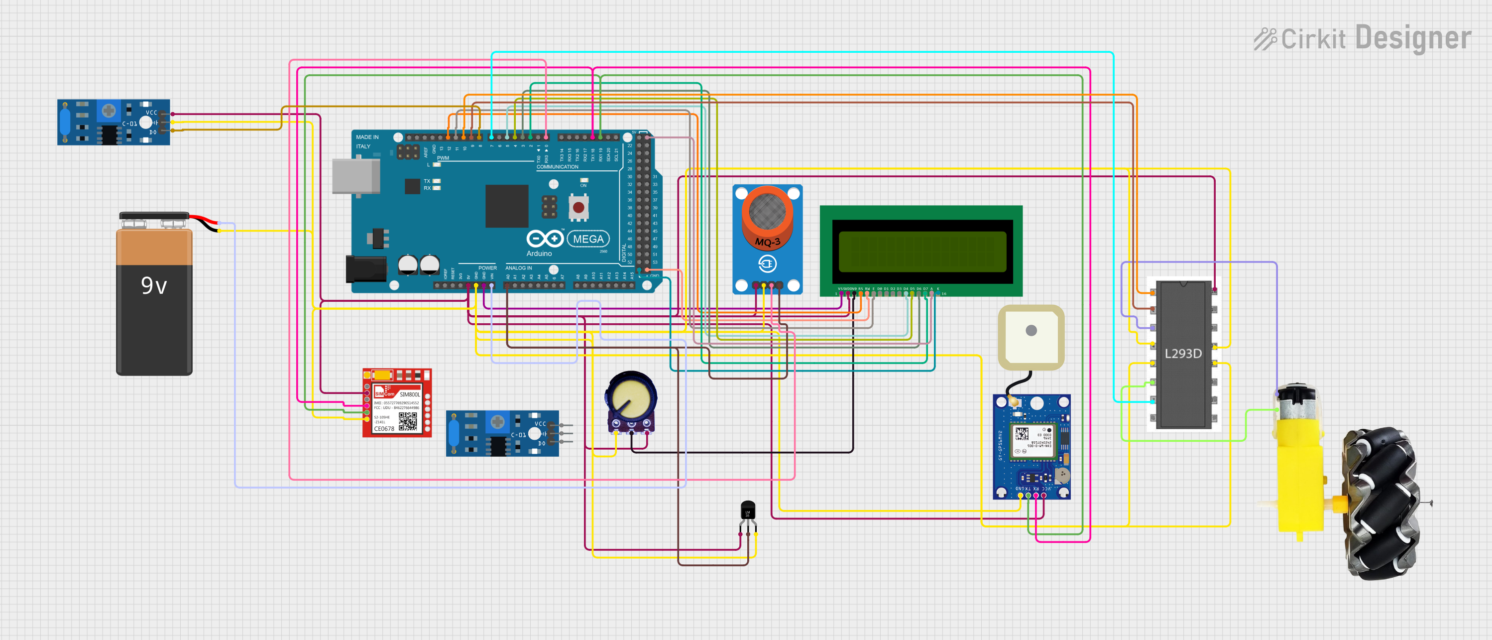
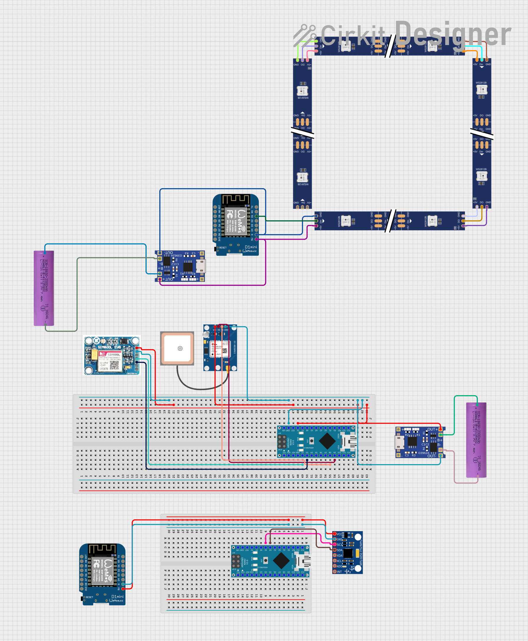
Explore Projects Built with ATGM336H
Common Applications and Use Cases
- Inclination and tilt sensing in robotics
- Vehicle level and tilt monitoring
- Antenna or solar panel positioning for optimal orientation
- Structural health monitoring for buildings and infrastructure
- Industrial equipment angle measurement
Technical Specifications
Key Technical Details
- Supply Voltage (Vcc): 3.0V to 5.5V
- Operating Current: 2mA (typical)
- Measurement Range: ±90 degrees
- Resolution: 0.1 degree
- Output: SPI/I2C digital interface
- Operating Temperature Range: -40°C to +85°C
Pin Configuration and Descriptions
| Pin Number | Pin Name | Description |
|---|---|---|
| 1 | VCC | Power supply (3.0V to 5.5V) |
| 2 | GND | Ground |
| 3 | SCL/SCLK | I2C clock/SPI clock input |
| 4 | SDA/MOSI | I2C data/SPI Master Out Slave In |
| 5 | SA0/MISO | I2C address select/SPI Master In Slave Out |
| 6 | CS | Chip select for SPI interface |
Usage Instructions
How to Use the Component in a Circuit
- Power Supply: Connect the VCC pin to a 3.0V to 5.5V power source and the GND pin to the ground of your system.
- Communication Interface: Choose between SPI or I2C for communication. For I2C, connect SCL to the I2C clock line and SDA to the I2C data line. For SPI, connect SCLK to the SPI clock, MOSI to Master Out Slave In, MISO to Master In Slave Out, and CS to the chip select pin.
- Mounting: Ensure the sensor is mounted securely and in the correct orientation for accurate measurements.
Important Considerations and Best Practices
- Avoid mechanical stress and ensure proper alignment during installation.
- Keep the sensor away from heat sources to prevent drift in readings.
- Use proper decoupling capacitors close to the power supply pins to minimize power supply noise.
- For SPI communication, ensure that the CS pin is toggled correctly to enable and disable the sensor.
Troubleshooting and FAQs
Common Issues Users Might Face
- Inaccurate Readings: Ensure the sensor is mounted correctly and there are no vibrations affecting the measurements.
- Communication Errors: Check the wiring and connections for the selected communication protocol. Ensure pull-up resistors are in place for I2C communication.
- No Output Signal: Verify that the power supply is within the specified range and the sensor is properly grounded.
Solutions and Tips for Troubleshooting
- Double-check the orientation and mounting of the sensor.
- Use an oscilloscope to check the integrity of the communication signals.
- Ensure that the microcontroller and sensor are configured for the same communication protocol and settings.
FAQs
Q: Can the ATGM336H be used outdoors? A: Yes, but it should be protected from direct exposure to water and extreme environmental conditions.
Q: What is the default communication protocol when the sensor is powered up? A: The default communication protocol is typically I2C, but it is advisable to check the datasheet or with the manufacturer for confirmation.
Q: How can I change the I2C address of the sensor? A: The I2C address can be changed by connecting the SA0/MISO pin to VCC or GND, depending on the desired address.
Q: Is there a need for calibration? A: The sensor is factory-calibrated, but for critical applications, field calibration might be necessary to account for any mounting misalignments or environmental factors.
Example Code for Arduino UNO
Below is an example of how to interface the ATGM336H with an Arduino UNO using the I2C protocol. This code assumes the default I2C address for the sensor.
#include <Wire.h>

// ATGM336H I2C address (check datasheet for your device's address)
#define ATGM336H_I2C_ADDRESS 0x68

void setup() {
  Wire.begin(); // Initialize I2C
  Serial.begin(9600); // Start serial communication at 9600 baud
}

void loop() {
  int16_t tiltAngle = readTiltAngle();
  Serial.print("Tilt Angle: ");
  Serial.println(tiltAngle);
  delay(1000); // Read every second
}

int16_t readTiltAngle() {
  Wire.beginTransmission(ATGM336H_I2C_ADDRESS);
  // Request 2 bytes from the sensor
  Wire.requestFrom(ATGM336H_I2C_ADDRESS, 2);
  while (Wire.available() < 2); // Wait for the data

  int16_t angle = Wire.read(); // Read the first byte
  angle |= Wire.read() << 8; // Read the second byte and combine
  Wire.endTransmission();

  return angle;
}
This code initializes the I2C communication, reads the tilt angle from the ATGM336H sensor, and outputs the result to the serial monitor. Remember to install the Wire library if it's not already included in your Arduino IDE.