How to Use UPixels T101-Plus: Examples, Pinouts, and Specs
Introduction
The UPixels T101-Plus is a versatile LED display module designed for creating dynamic visual effects and interactive installations. Manufactured by Upixels, this module features a high-resolution pixel matrix that delivers vibrant color displays and customizable animations. Its compact design and advanced functionality make it an excellent choice for a wide range of applications, including:
- Art installations and creative projects
- Advertising displays and digital signage
- Event lighting and stage effects
- Interactive exhibits and educational tools
With its ease of integration and support for various control protocols, the T101-Plus is a powerful tool for both hobbyists and professionals.
Explore Projects Built with UPixels T101-Plus

Explore Projects Built with UPixels T101-Plus
Technical Specifications
Key Technical Details
| Parameter | Specification |
|---|---|
| Manufacturer | Upixels |
| Model | T101-Plus |
| Pixel Matrix Resolution | 16x16 (256 individual RGB LEDs) |
| LED Type | WS2812B (individually addressable RGB) |
| Operating Voltage | 5V DC |
| Power Consumption | Max 15W |
| Communication Protocol | SPI or Serial (customizable) |
| Refresh Rate | Up to 60Hz |
| Dimensions | 160mm x 160mm x 10mm |
| Weight | 150g |
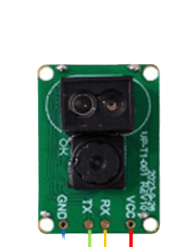
Pin Configuration and Descriptions
The UPixels T101-Plus module has a simple pinout for easy integration into your projects. Below is the pin configuration:
| Pin Name | Pin Number | Description |
|---|---|---|
| VCC | 1 | Power input (5V DC) |
| GND | 2 | Ground |
| DIN | 3 | Data input for LED control |
| DOUT | 4 | Data output for chaining multiple modules |
| CLK | 5 | Clock signal input (optional, for SPI) |
Usage Instructions
How to Use the Component in a Circuit
- Power Supply: Connect the
VCCpin to a stable 5V DC power source and theGNDpin to ground. Ensure the power supply can handle the maximum current draw of the module (up to 3A at full brightness). - Data Input: Connect the
DINpin to the data output pin of your microcontroller (e.g., Arduino, Raspberry Pi). For SPI communication, also connect theCLKpin to the clock output of your microcontroller. - Chaining Modules: To chain multiple T101-Plus modules, connect the
DOUTpin of the first module to theDINpin of the next module. - Programming: Use libraries such as Adafruit NeoPixel or FastLED to control the LED matrix. These libraries simplify the process of sending data to the module.
Important Considerations and Best Practices
- Power Management: If using multiple modules, ensure your power supply can handle the combined current draw. Consider using a capacitor (e.g., 1000µF) across the
VCCandGNDpins to stabilize the voltage. - Data Signal Integrity: Use a resistor (330-500Ω) in series with the
DINline to reduce noise and protect the LEDs. - Heat Dissipation: At full brightness, the module can generate heat. Ensure adequate ventilation or heat sinking if used for extended periods.
- Voltage Levels: The
DINpin expects a 5V logic level. If using a 3.3V microcontroller, use a level shifter to avoid communication issues.
Example Code for Arduino UNO
Below is an example of how to control the UPixels T101-Plus using the Adafruit NeoPixel library:
#include <Adafruit_NeoPixel.h>

// Define the number of LEDs in the matrix
#define NUM_LEDS 256

// Define the data pin connected to the DIN pin of the T101-Plus
#define DATA_PIN 6

// Create a NeoPixel object
Adafruit_NeoPixel strip = Adafruit_NeoPixel(NUM_LEDS, DATA_PIN, NEO_GRB + NEO_KHZ800);

void setup() {
  strip.begin(); // Initialize the NeoPixel library
  strip.show();  // Turn off all LEDs initially
}

void loop() {
  // Example: Fill the matrix with red color
  for (int i = 0; i < NUM_LEDS; i++) {
    strip.setPixelColor(i, strip.Color(255, 0, 0)); // Set pixel to red
  }
  strip.show(); // Update the display
  delay(1000);  // Wait for 1 second

  // Example: Turn off all LEDs
  for (int i = 0; i < NUM_LEDS; i++) {
    strip.setPixelColor(i, strip.Color(0, 0, 0)); // Turn off pixel
  }
  strip.show(); // Update the display
  delay(1000);  // Wait for 1 second
}
Troubleshooting and FAQs
Common Issues and Solutions
No LEDs Lighting Up
- Cause: Incorrect wiring or insufficient power supply.
- Solution: Double-check all connections, ensure the power supply is 5V and can provide sufficient current.
Flickering or Unstable Colors
- Cause: Noise in the data line or insufficient power.
- Solution: Add a 330-500Ω resistor in series with the
DINline and a capacitor (1000µF) acrossVCCandGND.
Module Overheating
- Cause: Prolonged use at full brightness.
- Solution: Reduce brightness in your code or improve ventilation around the module.
Data Signal Not Reaching All LEDs
- Cause: Signal degradation over long distances.
- Solution: Use shorter wires or add a signal booster between modules.
FAQs
Q: Can I use a 3.3V microcontroller with the T101-Plus?
A: Yes, but you will need a logic level shifter to convert the 3.3V data signal to 5V.
Q: How many modules can I chain together?
A: The number of modules you can chain depends on your power supply and the microcontroller's memory. For large installations, consider using a separate power supply for each module.
Q: What is the maximum refresh rate of the T101-Plus?
A: The module supports a refresh rate of up to 60Hz, depending on the number of LEDs and the microcontroller's processing speed.
Q: Can I control the T101-Plus with a Raspberry Pi?
A: Yes, the T101-Plus is compatible with Raspberry Pi. Use libraries like rpi_ws281x to control the LEDs.
This concludes the documentation for the UPixels T101-Plus. For further assistance, refer to the manufacturer's datasheet or contact Upixels support.