How to Use LED: Two Pin (red) - Long Pins: Examples, Pinouts, and Specs
Introduction
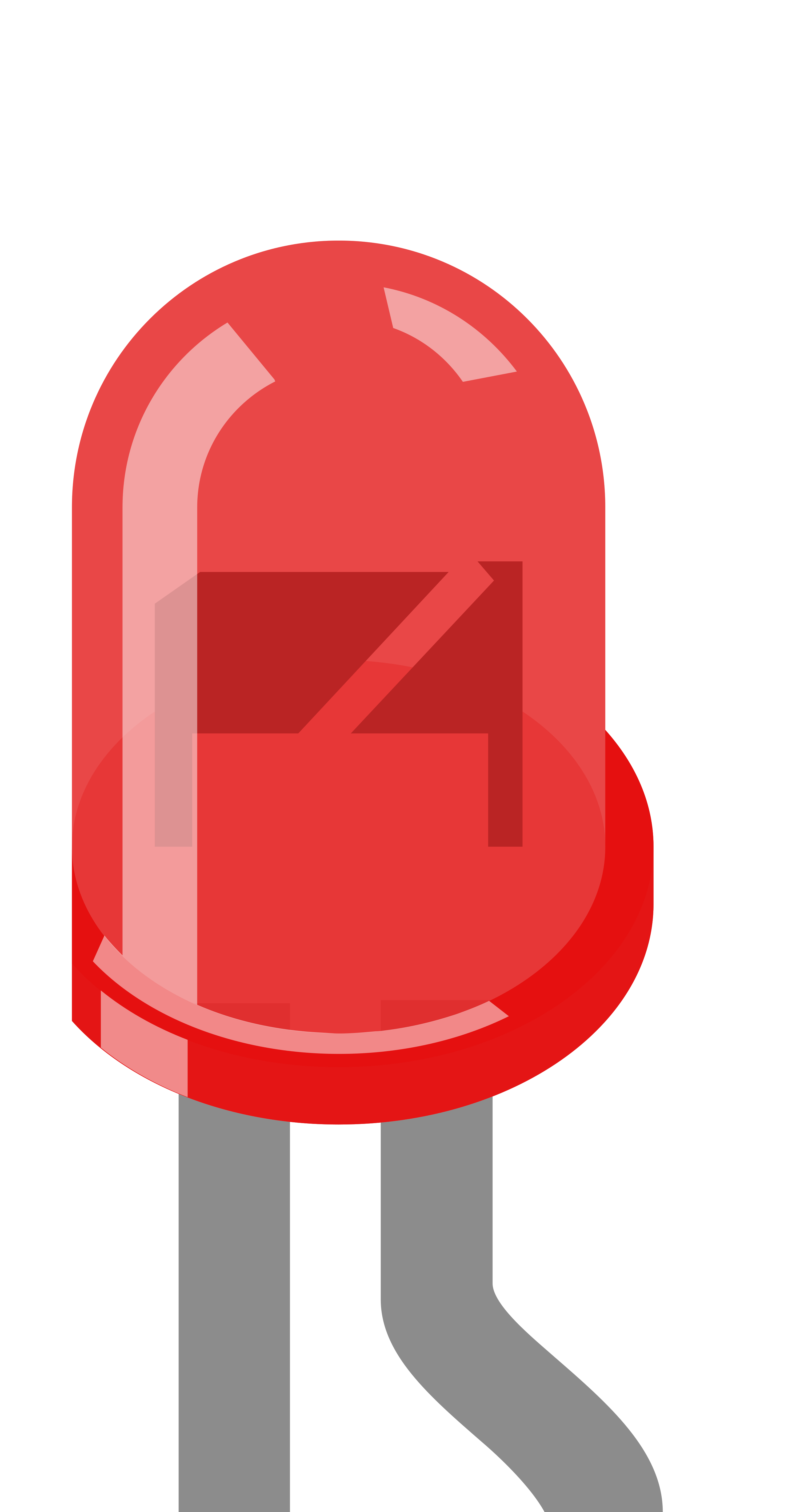
A light-emitting diode (LED) is a semiconductor device that emits light when an electric current flows through it. This particular LED emits red light and features two pins for easy integration into electronic circuits. The longer pin is the anode (positive terminal), while the shorter pin is the cathode (negative terminal), simplifying proper orientation during installation.
Explore Projects Built with LED: Two Pin (red) - Long Pins

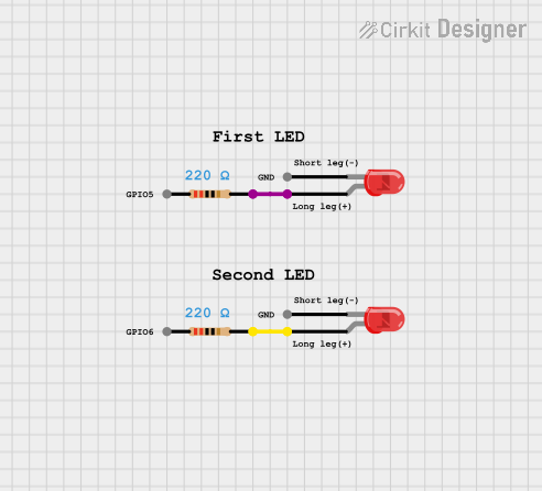
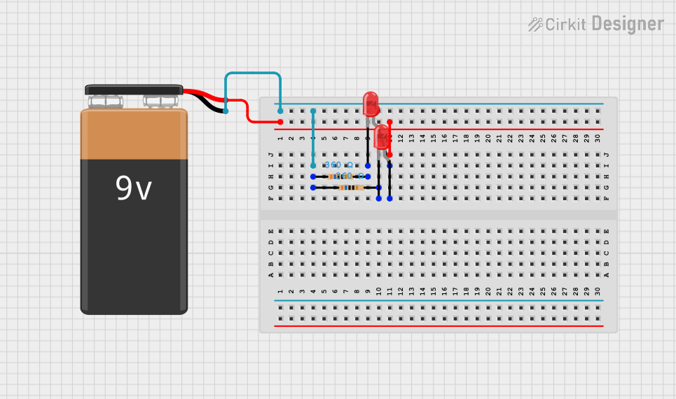
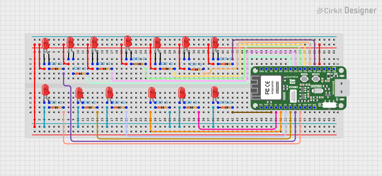
Explore Projects Built with LED: Two Pin (red) - Long Pins
Common Applications and Use Cases
- Indicator lights in electronic devices
- Status indicators in circuits
- Decorative lighting
- DIY electronics projects
- Educational kits for learning basic electronics
Technical Specifications
Below are the key technical details for the Two Pin Red LED:
| Parameter | Value |
|---|---|
| Forward Voltage (Vf) | 1.8V to 2.2V |
| Forward Current (If) | 20mA (typical) |
| Maximum Current (Imax) | 30mA |
| Wavelength | 620nm to 630nm (red light) |
| Viewing Angle | 20° to 30° |
| Operating Temperature | -40°C to +85°C |
| Pin Length | Anode: ~25mm, Cathode: ~20mm |
Pin Configuration and Descriptions
| Pin | Name | Description |
|---|---|---|
| Long Pin | Anode (+) | Connect to the positive terminal of the power source. |
| Short Pin | Cathode (-) | Connect to the negative terminal or ground. |
Usage Instructions
How to Use the Component in a Circuit
Identify the Pins: The longer pin is the anode (+), and the shorter pin is the cathode (-).
Connect to Power Source:
- Connect the anode to the positive terminal of the power source.
- Connect the cathode to the negative terminal or ground.
Use a Current-Limiting Resistor: To prevent damage to the LED, always use a resistor in series with the LED. Calculate the resistor value using Ohm's Law: [ R = \frac{V_{supply} - V_f}{I_f} ] Where:
- (V_{supply}) is the supply voltage.
- (V_f) is the forward voltage of the LED (1.8V to 2.2V).
- (I_f) is the forward current (20mA or 0.02A).
For example, if (V_{supply} = 5V): [ R = \frac{5V - 2V}{0.02A} = 150\Omega ]
Test the Circuit: Once connected, the LED should emit red light when powered.
Important Considerations and Best Practices
- Polarity Matters: Ensure the anode and cathode are connected correctly. Reversing the polarity may damage the LED.
- Avoid Overcurrent: Always use a current-limiting resistor to prevent excessive current from flowing through the LED.
- Heat Management: While LEDs generate minimal heat, ensure proper ventilation in high-power applications.
- Series or Parallel Connections: For multiple LEDs, consider whether to connect them in series or parallel, depending on your circuit design.
Example: Connecting to an Arduino UNO
Below is an example of how to connect the red LED to an Arduino UNO and make it blink:
Circuit Setup
- Connect the anode (long pin) of the LED to a 220Ω resistor.
- Connect the other end of the resistor to digital pin 13 on the Arduino.
- Connect the cathode (short pin) of the LED to the Arduino's GND pin.
Arduino Code
// This code makes the red LED blink on and off every second.

void setup() {
  pinMode(13, OUTPUT); // Set digital pin 13 as an output pin
}

void loop() {
  digitalWrite(13, HIGH); // Turn the LED on
  delay(1000);            // Wait for 1 second
  digitalWrite(13, LOW);  // Turn the LED off
  delay(1000);            // Wait for 1 second
}
Troubleshooting and FAQs
Common Issues and Solutions
LED Does Not Light Up
Cause: Incorrect polarity.
Solution: Ensure the anode (long pin) is connected to the positive terminal and the cathode (short pin) to the negative terminal.
Cause: No current-limiting resistor or incorrect resistor value.
Solution: Use a resistor with the correct value (e.g., 150Ω to 220Ω for a 5V supply).
LED is Dim
- Cause: Insufficient current.
- Solution: Check the resistor value and ensure it allows enough current (20mA typical).
LED Burns Out
- Cause: Excessive current.
- Solution: Always use a current-limiting resistor to protect the LED.
LED Flickers
- Cause: Unstable power supply.
- Solution: Use a stable power source or add a capacitor to smooth out voltage fluctuations.
FAQs
Q: Can I connect the LED directly to a 3.3V or 5V power source without a resistor?
A: No, doing so may damage the LED due to excessive current. Always use a current-limiting resistor.
Q: Can I use this LED with a 12V power supply?
A: Yes, but you must calculate and use an appropriate resistor to limit the current.
Q: How do I know if the LED is damaged?
A: If the LED does not light up even when connected correctly with a proper resistor, it may be damaged.
Q: Can I use this LED for PWM (Pulse Width Modulation) applications?
A: Yes, this LED is suitable for PWM applications, such as dimming or creating light patterns.