
How to Use N35P112: Examples, Pinouts, and Specs
 Design with N35P112 in Cirkit Designer
Introduction
The N35P112 is a high-performance N-channel MOSFET (Metal-Oxide-Semiconductor Field-Effect Transistor) designed for high-speed switching applications. It is characterized by its low on-resistance and fast switching capabilities, making it an ideal choice for power management, signal amplification, and other electronic circuit applications. Its compact design and efficiency make it suitable for use in a wide range of devices, including power supplies, motor drivers, and LED drivers.
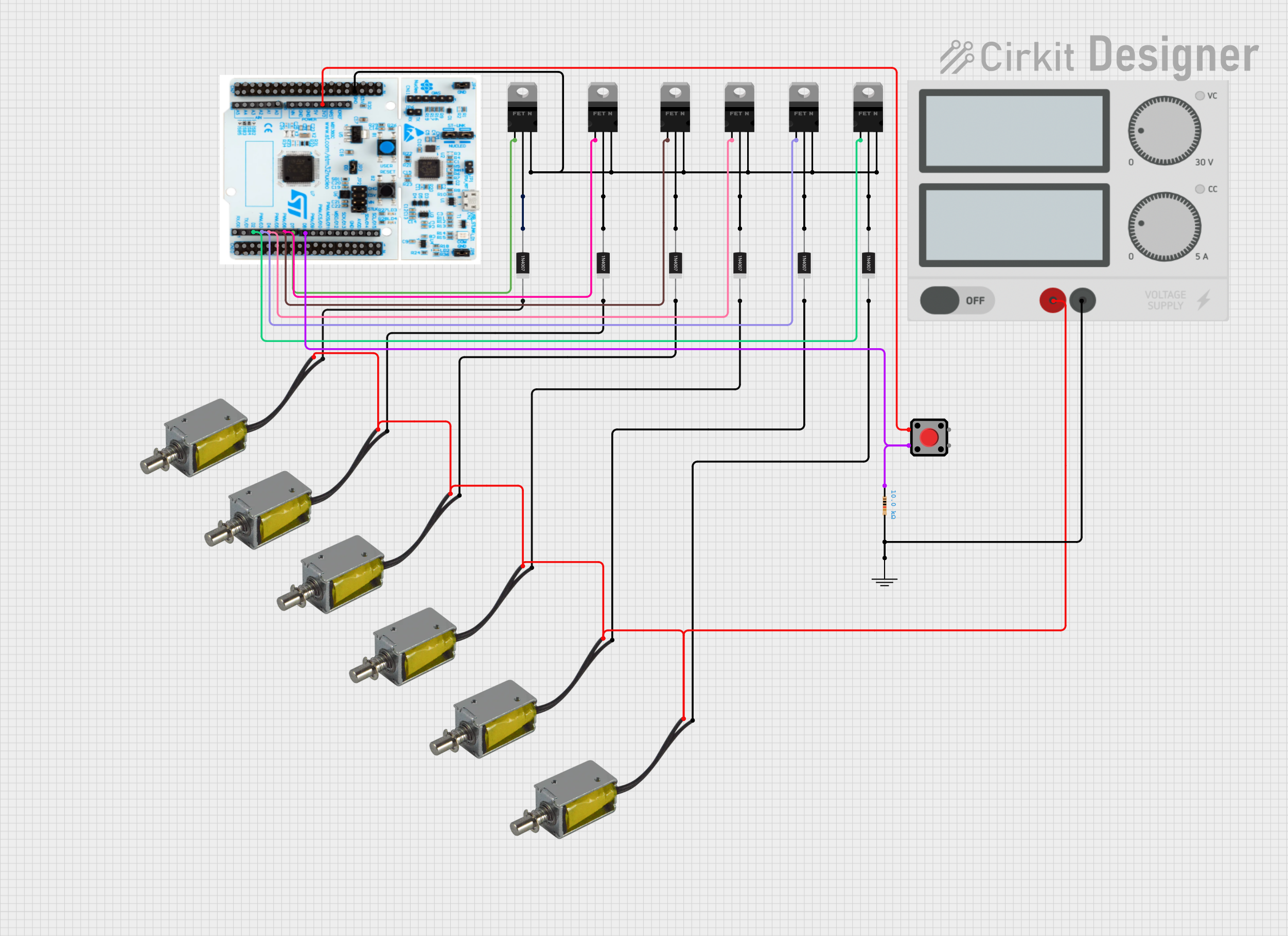
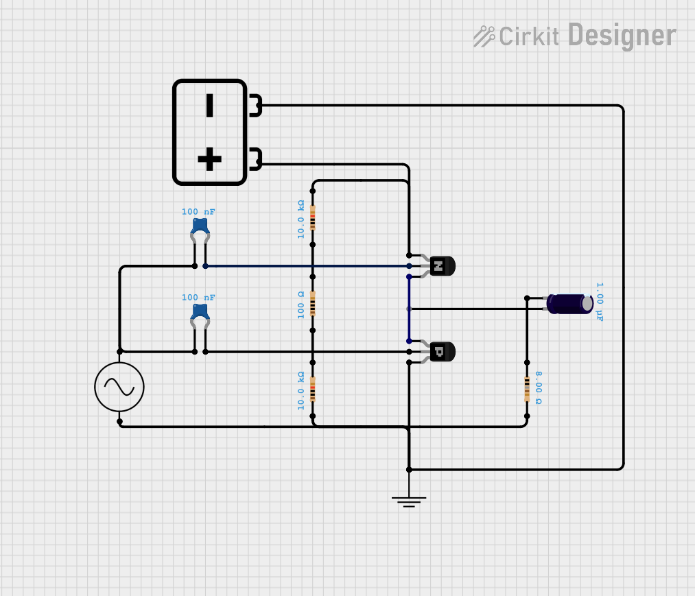
Explore Projects Built with N35P112
 Open Project in Cirkit Designer
 Open Project in Cirkit Designer
 Open Project in Cirkit Designer
 Open Project in Cirkit Designer
Explore Projects Built with N35P112
Open Project in Cirkit DesignerOpen Project in Cirkit DesignerOpen Project in Cirkit DesignerOpen Project in Cirkit DesignerCommon Applications
- Power management in DC-DC converters
- Signal amplification in audio and RF circuits
- Motor control and driver circuits
- LED lighting systems
- High-speed switching in digital circuits
Technical Specifications
The following table outlines the key technical specifications of the N35P112 MOSFET:
| Parameter | Value | Description |
|---|---|---|
| Drain-Source Voltage (VDS) | 30V | Maximum voltage between drain and source |
| Gate-Source Voltage (VGS) | ±20V | Maximum voltage between gate and source |
| Continuous Drain Current (ID) | 10A | Maximum current through the drain |
| Pulsed Drain Current (IDM) | 40A | Maximum pulsed current through the drain |
| On-Resistance (RDS(on)) | 0.015Ω | Resistance when the MOSFET is on |
| Gate Threshold Voltage (VGS(th)) | 1.2V - 2.5V | Voltage required to turn on the MOSFET |
| Total Gate Charge (Qg) | 12nC | Charge required to fully switch the gate |
| Power Dissipation (PD) | 25W | Maximum power dissipation |
| Operating Temperature Range | -55°C to +150°C | Safe operating temperature range |
| Package Type | TO-220, SOT-23, or DPAK | Available package options |
Pin Configuration
The N35P112 MOSFET typically comes in a 3-pin configuration. Below is the pinout description for the TO-220 package:
| Pin Number | Pin Name | Description |
|---|---|---|
| 1 | Gate | Controls the MOSFET switching |
| 2 | Drain | Current flows from drain to source |
| 3 | Source | Connected to ground or load return path |
Usage Instructions
How to Use the N35P112 in a Circuit
- Gate Control: Connect the gate pin to a control signal (e.g., from a microcontroller or driver circuit). Ensure the gate voltage (VGS) is within the specified range (±20V).
- Drain-Source Connection: Connect the drain pin to the positive side of the load and the source pin to the ground or return path.
- Gate Resistor: Use a resistor (typically 10Ω to 100Ω) in series with the gate to limit inrush current and prevent damage to the gate.
- Flyback Diode: For inductive loads (e.g., motors or relays), add a flyback diode across the load to protect the MOSFET from voltage spikes.
- Heat Dissipation: If operating at high currents, attach a heatsink to the MOSFET to manage heat dissipation.
Example Circuit with Arduino UNO
The following example demonstrates how to use the N35P112 to control an LED strip with an Arduino UNO:
Circuit Connections
- Gate: Connect to Arduino digital pin 9 through a 100Ω resistor.
- Drain: Connect to the positive terminal of the LED strip.
- Source: Connect to ground.
- Power Supply: Connect the LED strip's negative terminal to the power supply ground and its positive terminal to the power supply's positive output.
Arduino Code
// Example code to control an LED strip using the N35P112 MOSFET
// Connect the MOSFET gate to pin 9 of the Arduino through a 100Ω resistor

const int mosfetGatePin = 9; // Pin connected to the MOSFET gate

void setup() {
  pinMode(mosfetGatePin, OUTPUT); // Set the MOSFET gate pin as an output
}

void loop() {
  digitalWrite(mosfetGatePin, HIGH); // Turn on the MOSFET (LED strip ON)
  delay(1000); // Keep the LED strip ON for 1 second
  digitalWrite(mosfetGatePin, LOW);  // Turn off the MOSFET (LED strip OFF)
  delay(1000); // Keep the LED strip OFF for 1 second
}
Best Practices
- Avoid exceeding the maximum voltage and current ratings to prevent damage.
- Use proper heat dissipation techniques, such as heatsinks or cooling fans, for high-power applications.
- Ensure the gate voltage is sufficient to fully turn on the MOSFET (above VGS(th)).
Troubleshooting and FAQs
Common Issues
MOSFET Overheating
- Cause: Exceeding the power dissipation limit or insufficient heat dissipation.
- Solution: Use a heatsink or reduce the current through the MOSFET.
MOSFET Not Switching
- Cause: Insufficient gate voltage or incorrect wiring.
- Solution: Verify the gate voltage is above the threshold (VGS(th)) and check the circuit connections.
Voltage Drop Across MOSFET
- Cause: High on-resistance (RDS(on)) or insufficient gate drive.
- Solution: Ensure the gate voltage is high enough to minimize RDS(on).
FAQs
Q1: Can the N35P112 be used for AC applications?
A1: The N35P112 is primarily designed for DC applications. For AC applications, additional circuitry such as a rectifier may be required.
Q2: What is the maximum PWM frequency for the N35P112?
A2: The maximum PWM frequency depends on the gate charge (Qg) and the gate driver capability. Typically, it can handle frequencies up to 100kHz with proper gate drive.
Q3: How do I protect the MOSFET from voltage spikes?
A3: Use a flyback diode across inductive loads and consider adding a TVS (Transient Voltage Suppressor) diode for additional protection.
This concludes the documentation for the N35P112 MOSFET.