How to Use Coborator Reglabil 12A Servo: Examples, Pinouts, and Specs
Introduction
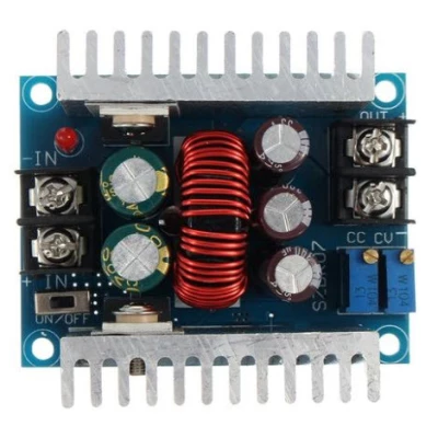
The Coborator Reglabil 12A Servo is a high-power variable resistor or adjustable power supply designed to handle currents of up to 12A. This component is commonly used in applications requiring precise control of servo motors, such as robotics, industrial automation, and remote-controlled systems. By adjusting the output voltage or resistance, users can control the speed, torque, or position of servo motors with high accuracy.
Explore Projects Built with Coborator Reglabil 12A Servo

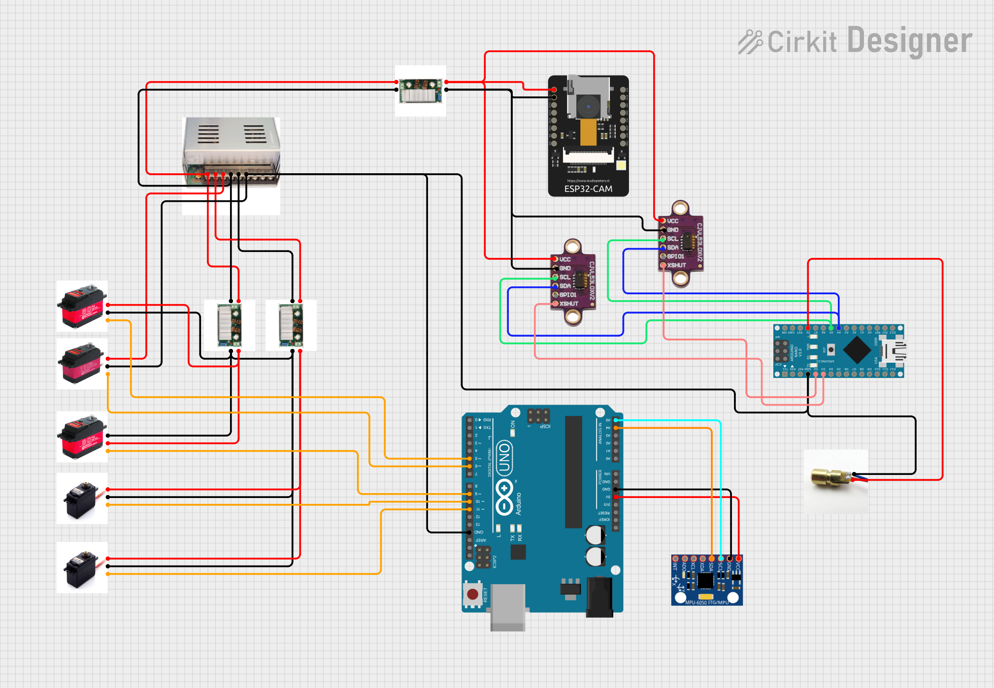

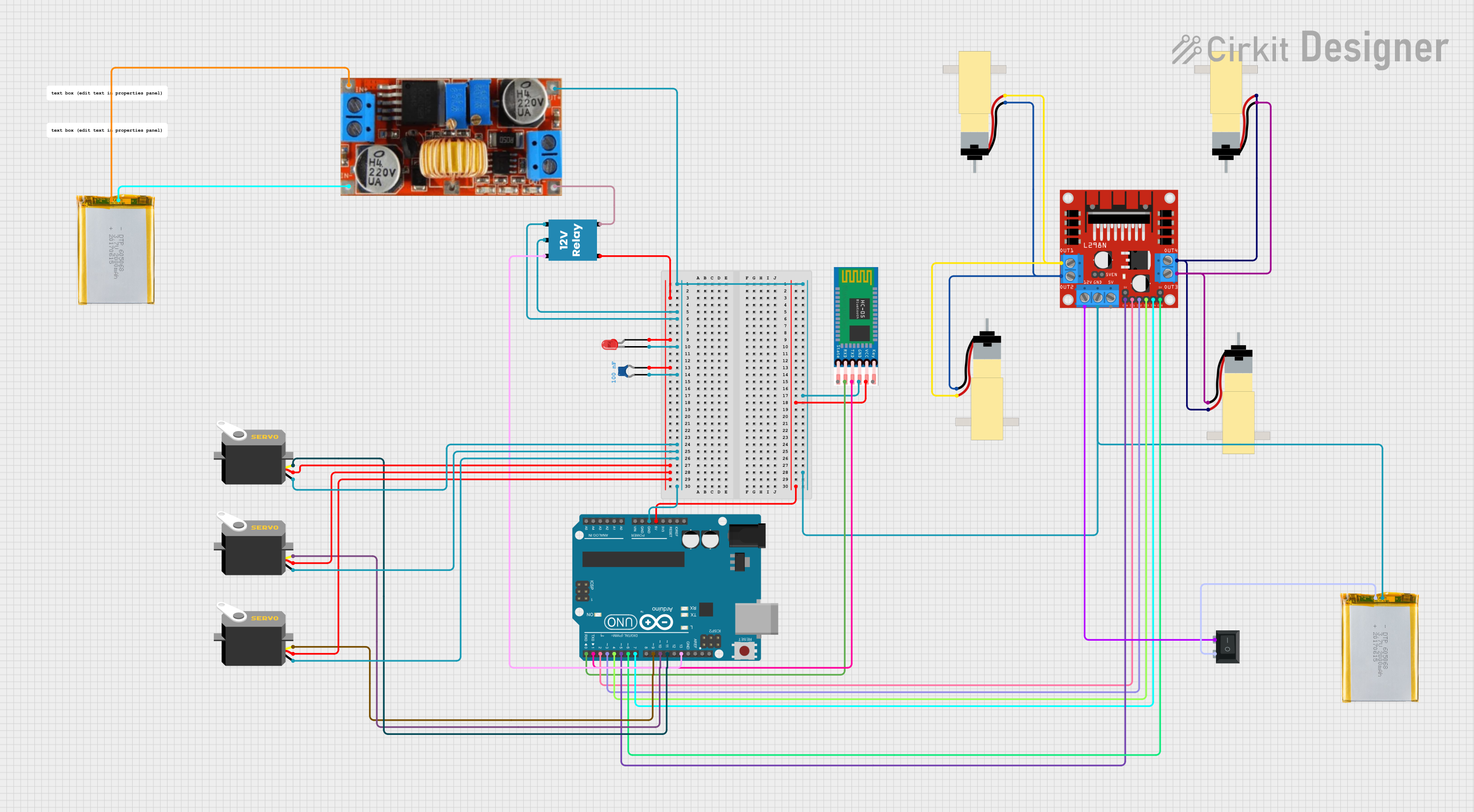
Explore Projects Built with Coborator Reglabil 12A Servo
Common Applications:
- Servo motor speed and position control
- Robotics and automation systems
- Remote-controlled vehicles and drones
- Adjustable power supply for high-current devices
- Prototyping and testing of motorized systems
Technical Specifications
The following table outlines the key technical details of the Coborator Reglabil 12A Servo:
| Parameter | Value |
|---|---|
| Maximum Current | 12A |
| Input Voltage Range | 5V to 24V |
| Output Voltage Range | 0V to Input Voltage |
| Resistance Range | Adjustable (0Ω to 10kΩ) |
| Power Dissipation | Up to 300W |
| Control Type | Rotary knob or digital input |
| Operating Temperature | -20°C to 85°C |
| Dimensions | 50mm x 40mm x 30mm |
Pin Configuration and Descriptions
The Coborator Reglabil 12A Servo typically has the following pin configuration:
| Pin Name | Description |
|---|---|
| VIN | Input voltage (5V to 24V) |
| GND | Ground connection |
| VOUT | Adjustable output voltage |
| CTRL | Control pin for digital adjustment (optional) |
Usage Instructions
How to Use the Component in a Circuit
Connect the Input Voltage:
- Connect the VIN pin to a DC power source (5V to 24V) capable of supplying sufficient current for your application.
- Connect the GND pin to the ground of the power source.
Connect the Load:
- Attach the load (e.g., a servo motor) to the VOUT pin and GND pin.
- Ensure the load does not exceed the maximum current rating of 12A.
Adjust the Output:
- Use the rotary knob to manually adjust the output voltage or resistance.
- If the component supports digital control, connect the CTRL pin to a microcontroller (e.g., Arduino) for precise adjustments.
Power On:
- Turn on the power supply and monitor the output voltage using a multimeter if needed.
- Gradually adjust the output to the desired level.
Important Considerations and Best Practices
- Heat Dissipation: The component may generate significant heat at high currents. Use a heatsink or active cooling to prevent overheating.
- Current Limitation: Ensure the connected load does not exceed the 12A current limit to avoid damage.
- Voltage Matching: Verify that the input voltage is within the specified range and matches the requirements of the connected load.
- Digital Control: If using the CTRL pin, ensure the control signal is within the acceptable voltage range (typically 0V to 5V).
Example: Using with an Arduino UNO
The Coborator Reglabil 12A Servo can be controlled digitally using an Arduino UNO. Below is an example code snippet to adjust the output voltage using PWM:
// Example: Controlling Coborator Reglabil 12A Servo with Arduino UNO
// This code generates a PWM signal to adjust the output voltage via the CTRL pin.

const int ctrlPin = 9; // Connect CTRL pin of the component to Arduino pin 9

void setup() {
  pinMode(ctrlPin, OUTPUT); // Set the CTRL pin as an output
}

void loop() {
  // Gradually increase the output voltage
  for (int dutyCycle = 0; dutyCycle <= 255; dutyCycle++) {
    analogWrite(ctrlPin, dutyCycle); // Write PWM signal to CTRL pin
    delay(10); // Wait 10ms before increasing the duty cycle
  }

  // Gradually decrease the output voltage
  for (int dutyCycle = 255; dutyCycle >= 0; dutyCycle--) {
    analogWrite(ctrlPin, dutyCycle); // Write PWM signal to CTRL pin
    delay(10); // Wait 10ms before decreasing the duty cycle
  }
}
Note: The PWM signal adjusts the output voltage indirectly. Use a multimeter to verify the actual output voltage.
Troubleshooting and FAQs
Common Issues and Solutions
No Output Voltage:
- Cause: Input voltage is not connected or is outside the specified range.
- Solution: Verify the input voltage and ensure proper connections to VIN and GND.
Overheating:
- Cause: Excessive current draw or insufficient cooling.
- Solution: Ensure the load does not exceed 12A and use a heatsink or fan for cooling.
Inconsistent Output:
- Cause: Poor connections or interference on the CTRL pin.
- Solution: Check all connections and use shielded cables for the CTRL pin if necessary.
Servo Motor Not Responding:
- Cause: Output voltage is too low or incompatible with the servo motor.
- Solution: Adjust the output voltage to match the servo motor's specifications.
FAQs
Q1: Can I use this component with an AC power source?
A1: No, the Coborator Reglabil 12A Servo is designed for DC input only. Using an AC power source may damage the component.
Q2: What happens if the load exceeds 12A?
A2: Exceeding the current limit can cause overheating, damage to the component, or failure of the connected load. Always ensure the load is within the specified limits.
Q3: Can I control multiple servo motors with this component?
A3: Yes, as long as the total current draw of all connected motors does not exceed 12A.
Q4: Is the CTRL pin mandatory for operation?
A4: No, the CTRL pin is optional. You can manually adjust the output using the rotary knob if digital control is not required.