How to Use LED Signage: Examples, Pinouts, and Specs
Introduction
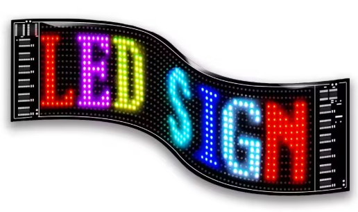
LED signage is a display technology that uses light-emitting diodes (LEDs) to convey information, advertisements, or messages. It is known for its bright, vibrant colors and energy efficiency, making it suitable for both indoor and outdoor applications. LED signage is widely used in retail stores, transportation hubs, sports arenas, and public spaces due to its high visibility and customizable design.
Explore Projects Built with LED Signage
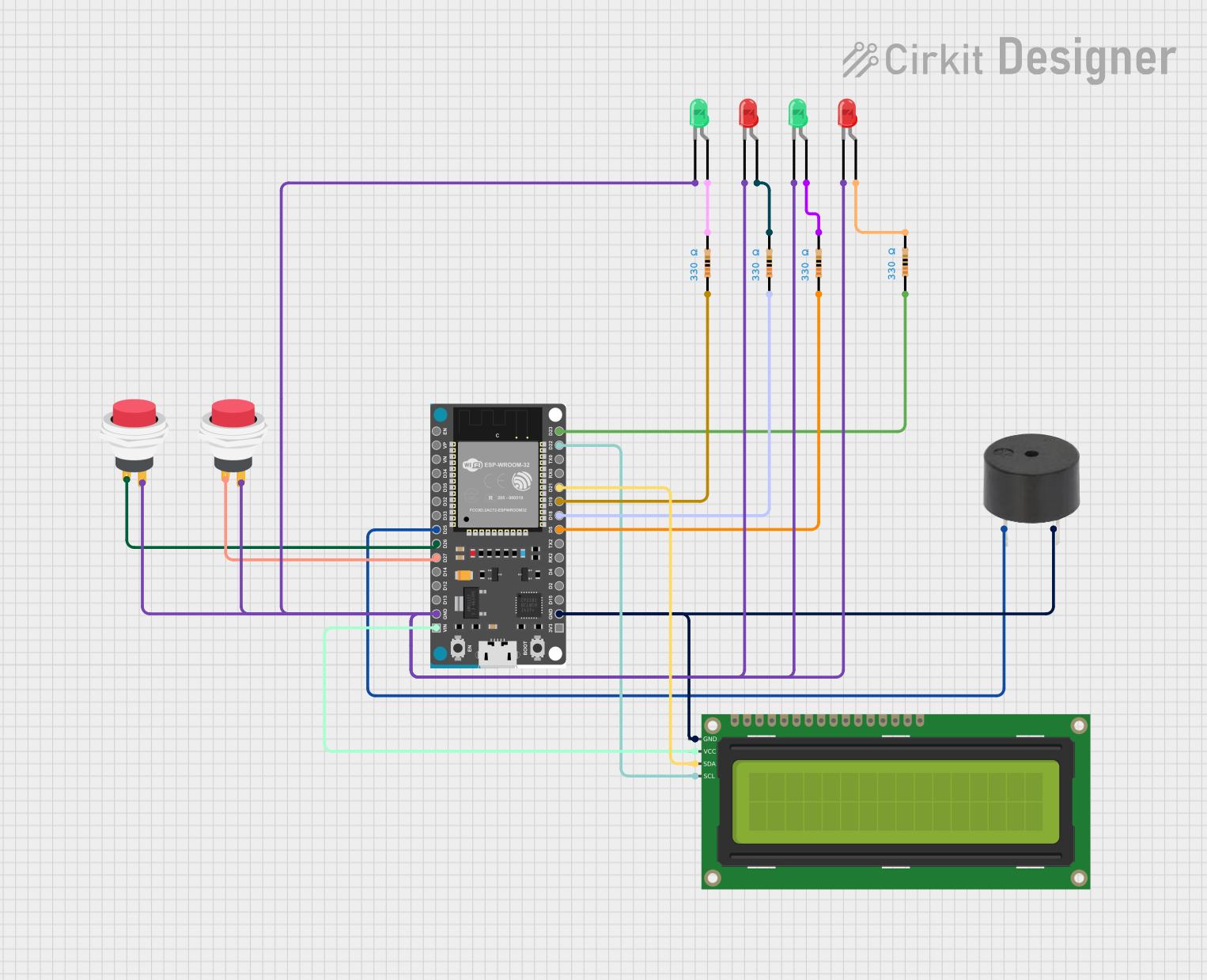


Explore Projects Built with LED Signage
Common Applications and Use Cases
- Retail and Advertising: Displaying promotional content, sales, and advertisements.
- Transportation: Showing schedules, directions, and alerts in bus stations, airports, and train stations.
- Public Information: Broadcasting announcements, weather updates, or emergency alerts.
- Entertainment and Events: Creating dynamic visuals for concerts, sports events, and exhibitions.
- Corporate Environments: Displaying company information, branding, or internal communications.
Technical Specifications
Key Technical Details
- Input Voltage: Typically 5V, 12V, or 24V DC (varies by model).
- Power Consumption: Depends on size and brightness; ranges from 10W to 300W.
- Pixel Pitch: Commonly 1.5mm to 10mm (distance between LED pixels).
- Brightness: 800 to 10,000 nits (suitable for indoor and outdoor use).
- Viewing Angle: 120° to 160° (horizontal and vertical).
- Operating Temperature: -20°C to 50°C.
- Lifespan: 50,000 to 100,000 hours.
Pin Configuration and Descriptions
The pin configuration for LED signage modules may vary depending on the manufacturer. Below is a general example for a common RGB LED signage module:
| Pin Name | Description |
|---|---|
| VCC | Power supply input (e.g., 5V or 12V DC). |
| GND | Ground connection. |
| R | Red LED control signal. |
| G | Green LED control signal. |
| B | Blue LED control signal. |
| CLK | Clock signal for data synchronization. |
| DATA | Serial data input for LED control. |
| LAT | Latch signal to update the display. |
| OE | Output enable for brightness control. |
Usage Instructions
How to Use the Component in a Circuit
- Power Supply: Ensure the power supply matches the voltage and current requirements of the LED signage module. Use a regulated DC power source to avoid damage.
- Controller: Connect the LED signage to a compatible controller, such as an Arduino, Raspberry Pi, or a dedicated LED driver board.
- Signal Connections: Wire the control pins (e.g., R, G, B, CLK, DATA) to the corresponding pins on the controller. Use proper connectors or soldering for secure connections.
- Programming: Use software libraries or protocols (e.g., SPI or I2C) to send data to the LED signage. For Arduino, libraries like
Adafruit_NeoPixelorFastLEDcan simplify programming. - Testing: Power on the circuit and upload a test program to verify the LED signage is functioning correctly.
Important Considerations and Best Practices
- Power Management: High-brightness LED signage can draw significant current. Use a power supply with sufficient capacity and consider adding capacitors to stabilize the voltage.
- Heat Dissipation: Ensure proper ventilation or heat sinks to prevent overheating, especially for outdoor or high-power applications.
- Weatherproofing: For outdoor use, choose LED signage with an IP65 or higher rating to protect against water and dust.
- Data Integrity: Use shielded cables for long data connections to minimize interference and signal loss.
- Brightness Control: Adjust brightness levels to suit the environment and reduce power consumption.
Example Code for Arduino UNO
Below is an example of controlling a simple RGB LED signage module using the FastLED library:
#include <FastLED.h>

// Define the number of LEDs in the signage
#define NUM_LEDS 16

// Define the data pin connected to the LED signage
#define DATA_PIN 6

// Create an array to hold the LED data
CRGB leds[NUM_LEDS];

void setup() {
  // Initialize the LED array
  FastLED.addLeds<WS2812, DATA_PIN, GRB>(leds, NUM_LEDS);
}

void loop() {
  // Set all LEDs to red
  for (int i = 0; i < NUM_LEDS; i++) {
    leds[i] = CRGB::Red; // Set the LED color to red
  }
  FastLED.show(); // Update the display
  delay(1000);    // Wait for 1 second

  // Set all LEDs to green
  for (int i = 0; i < NUM_LEDS; i++) {
    leds[i] = CRGB::Green; // Set the LED color to green
  }
  FastLED.show(); // Update the display
  delay(1000);    // Wait for 1 second

  // Set all LEDs to blue
  for (int i = 0; i < NUM_LEDS; i++) {
    leds[i] = CRGB::Blue; // Set the LED color to blue
  }
  FastLED.show(); // Update the display
  delay(1000);    // Wait for 1 second
}
Troubleshooting and FAQs
Common Issues and Solutions
LEDs Not Lighting Up:
- Cause: Incorrect wiring or insufficient power supply.
- Solution: Double-check all connections and ensure the power supply meets the voltage and current requirements.
Flickering or Unstable Display:
- Cause: Poor data signal or power fluctuations.
- Solution: Use shorter, shielded cables for data connections and add capacitors near the power input.
Incorrect Colors Displayed:
- Cause: Misconfigured RGB order or faulty LEDs.
- Solution: Verify the RGB order in the code (e.g., GRB, RGB) and replace any damaged LEDs.
Overheating:
- Cause: Prolonged use at maximum brightness or inadequate ventilation.
- Solution: Reduce brightness levels and ensure proper airflow around the signage.
FAQs
Can I use LED signage outdoors? Yes, but ensure the signage has an appropriate IP rating (e.g., IP65) for weather resistance.
What controller is best for LED signage? Arduino, Raspberry Pi, or dedicated LED driver boards are commonly used, depending on the complexity of the application.
How do I extend the lifespan of LED signage? Operate within the recommended voltage and brightness levels, and ensure proper cooling and maintenance.
Can I display animations on LED signage? Yes, animations can be programmed using libraries like
FastLEDorAdafruit_NeoPixelwith compatible controllers.