How to Use RJ45 Cat6 T568 Connectors: Examples, Pinouts, and Specs
Introduction
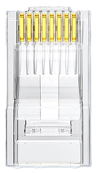
RJ45 Cat6 T568 Connectors are modular connectors used for terminating Ethernet cables, specifically designed for high-speed data transmission in networking applications. These connectors are compatible with Cat6 cables, which support gigabit Ethernet and higher data rates, making them ideal for modern networking environments. They follow the T568A or T568B wiring standards, ensuring proper pin configuration for reliable connectivity.
Explore Projects Built with RJ45 Cat6 T568 Connectors

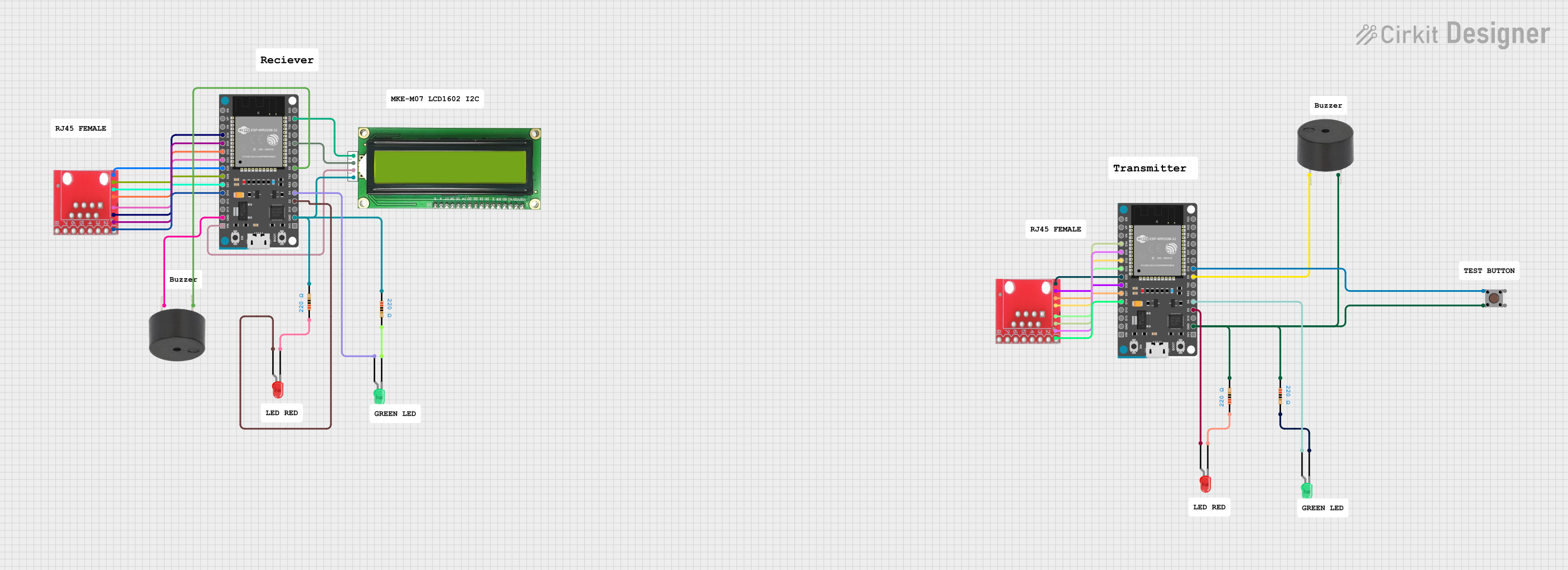


Explore Projects Built with RJ45 Cat6 T568 Connectors
Common Applications and Use Cases
- Ethernet networking for homes, offices, and data centers
- High-speed internet connections
- Structured cabling systems
- PoE (Power over Ethernet) devices such as IP cameras, VoIP phones, and wireless access points
- Network patch panels and wall jacks
Technical Specifications
Key Technical Details
- Connector Type: RJ45 (8P8C - 8 positions, 8 contacts)
- Cable Compatibility: Cat6 (23-24 AWG solid or stranded wires)
- Wiring Standards: T568A and T568B
- Data Transmission Speed: Up to 10 Gbps (depending on cable and network setup)
- Material: Gold-plated contacts for corrosion resistance and improved conductivity
- Operating Temperature: -40°C to 85°C
- Durability: Rated for 750+ mating cycles
Pin Configuration and Descriptions
The RJ45 Cat6 T568 Connectors use an 8-pin configuration. The pinout follows either the T568A or T568B wiring standard. Below is the pin configuration for both standards:
T568A Wiring Standard
| Pin Number | Wire Color | Signal Description |
|---|---|---|
| 1 | White/Green | Transmit Data + (TX+) |
| 2 | Green | Transmit Data - (TX-) |
| 3 | White/Orange | Receive Data + (RX+) |
| 4 | Blue | Unused (PoE Positive) |
| 5 | White/Blue | Unused (PoE Positive) |
| 6 | Orange | Receive Data - (RX-) |
| 7 | White/Brown | Unused (PoE Negative) |
| 8 | Brown | Unused (PoE Negative) |
T568B Wiring Standard
| Pin Number | Wire Color | Signal Description |
|---|---|---|
| 1 | White/Orange | Transmit Data + (TX+) |
| 2 | Orange | Transmit Data - (TX-) |
| 3 | White/Green | Receive Data + (RX+) |
| 4 | Blue | Unused (PoE Positive) |
| 5 | White/Blue | Unused (PoE Positive) |
| 6 | Green | Receive Data - (RX-) |
| 7 | White/Brown | Unused (PoE Negative) |
| 8 | Brown | Unused (PoE Negative) |
Usage Instructions
How to Use the Component in a Circuit
Prepare the Ethernet Cable:
- Strip approximately 1 inch of the outer jacket of the Cat6 cable using a cable stripper.
- Untwist the wire pairs and straighten them for easy insertion into the connector.
Arrange the Wires:
- Follow either the T568A or T568B wiring standard to arrange the wires in the correct order.
- Ensure the wires are aligned and trimmed to the same length.
Insert the Wires into the Connector:
- Slide the wires into the RJ45 connector, ensuring each wire is fully seated in its respective slot.
- Verify that the wire colors match the chosen wiring standard.
Crimp the Connector:
- Place the connector into an RJ45 crimping tool and apply firm pressure to secure the wires and contacts.
- Inspect the connector to ensure all pins are properly crimped and the wires are securely held.
Test the Connection:
- Use a cable tester to verify continuity and proper pinout configuration.
- If the test fails, recheck the wiring and re-crimp if necessary.
Important Considerations and Best Practices
- Always use high-quality RJ45 connectors and crimping tools to ensure reliable connections.
- Avoid excessive untwisting of wire pairs, as this can degrade signal performance.
- Use a cable tester to confirm proper wiring before deploying the cable in a network.
- When connecting to PoE devices, ensure the connector and cable meet the required power specifications.
Example: Connecting to an Arduino UNO
While RJ45 connectors are not directly used with an Arduino UNO, they can be part of an Ethernet shield or module. Below is an example of using an Ethernet shield with an Arduino UNO to connect to a network:
#include <SPI.h>
#include <Ethernet.h>

// MAC address and IP address for the Ethernet shield
byte mac[] = { 0xDE, 0xAD, 0xBE, 0xEF, 0xFE, 0xED };
IPAddress ip(192, 168, 1, 177);

// Initialize the Ethernet server on port 80
EthernetServer server(80);

void setup() {
  // Start the Ethernet connection
  Ethernet.begin(mac, ip);

  // Start the server
  server.begin();
  Serial.begin(9600);
  Serial.println("Server is ready at IP: ");
  Serial.println(Ethernet.localIP());
}

void loop() {
  // Listen for incoming clients
  EthernetClient client = server.available();
  if (client) {
    Serial.println("New client connected");
    // Send a response to the client
    client.println("Hello, Ethernet!");
    delay(100);
    client.stop();
  }
}
Troubleshooting and FAQs
Common Issues Users Might Face
Improper Wiring:
- Issue: The cable does not work or fails the cable tester.
- Solution: Double-check the wiring order (T568A or T568B) and ensure the wires are fully inserted into the connector.
Loose Connections:
- Issue: The connector feels loose or the connection is intermittent.
- Solution: Ensure the crimping tool is properly used to secure the connector. Replace the connector if necessary.
Signal Degradation:
- Issue: The network speed is slower than expected.
- Solution: Verify the cable length (should not exceed 100 meters for Cat6) and avoid excessive untwisting of wire pairs.
PoE Device Not Powering On:
- Issue: A PoE device does not receive power.
- Solution: Ensure the cable and connector meet the required power specifications for PoE.
Solutions and Tips for Troubleshooting
- Use a high-quality cable tester to identify wiring faults.
- Replace damaged connectors or cables to avoid intermittent issues.
- Ensure the RJ45 connectors are compatible with the cable type (solid or stranded).
- Keep the cable length within the recommended limits to maintain signal integrity.