How to Use PIC16F72: Examples, Pinouts, and Specs
Introduction
The PIC16F72 is an 8-bit microcontroller manufactured by SDR, based on Microchip Technology's architecture. It features a 14-bit instruction set, 2K words of program memory, 128 bytes of RAM, and 128 bytes of EEPROM. Designed for low-power applications, the PIC16F72 is equipped with versatile peripherals, including timers, comparators, and an integrated 8-channel, 8-bit ADC (Analog-to-Digital Converter). Its compact design and robust functionality make it ideal for a wide range of embedded systems.
Explore Projects Built with PIC16F72


Explore Projects Built with PIC16F72
Common Applications
- Home automation systems
- Industrial control systems
- Sensor interfacing and data acquisition
- Motor control applications
- Low-power IoT devices
Technical Specifications
Key Features
| Feature | Specification |
|---|---|
| Architecture | 8-bit |
| Instruction Set | 14-bit |
| Program Memory | 2K words |
| Data Memory (RAM) | 128 bytes |
| EEPROM | 128 bytes |
| Operating Voltage Range | 2.0V to 5.5V |
| Clock Speed | Up to 20 MHz (with external clock) |
| ADC | 8-channel, 8-bit resolution |
| Timers | 3 (Timer0, Timer1, Timer2) |
| Comparators | 2 |
| I/O Pins | 22 |
| Package Options | 28-pin DIP, SOIC, SSOP |
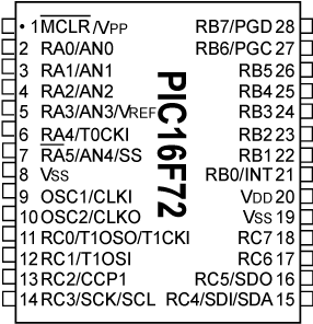
Pin Configuration
The PIC16F72 is available in a 28-pin package. Below is the pin configuration and description:
| Pin Number | Pin Name | Type | Description |
|---|---|---|---|
| 1 | RA2/AN2 | Analog/Digital I/O | Analog input 2 or digital I/O pin |
| 2 | RA3/AN3/VREF | Analog/Digital I/O | Analog input 3 or voltage reference |
| 3 | RA4/T0CKI | Digital I/O | Timer0 clock input or digital I/O |
| 4 | RA5/AN4 | Analog/Digital I/O | Analog input 4 or digital I/O pin |
| 5 | VSS | Power | Ground |
| 6 | OSC1/CLKIN | Input | Oscillator input or external clock |
| 7 | OSC2/CLKOUT | Output | Oscillator output |
| 8 | RC0/T1OSO | Digital I/O | Timer1 oscillator output or digital I/O |
| 9 | RC1/T1OSI | Digital I/O | Timer1 oscillator input or digital I/O |
| 10 | RC2/CCP1 | Digital I/O | Capture/Compare/PWM module 1 |
| ... | ... | ... | ... |
| 28 | RA0/AN0 | Analog/Digital I/O | Analog input 0 or digital I/O pin |
Note: For the full pinout, refer to the official datasheet.
Usage Instructions
Using the PIC16F72 in a Circuit
- Power Supply: Connect the VDD pin to a 5V power source and the VSS pin to ground.
- Oscillator Configuration: Use an external crystal oscillator (up to 20 MHz) connected to the OSC1 and OSC2 pins. Alternatively, use an RC oscillator for low-cost applications.
- Programming: Use an ICSP (In-Circuit Serial Programming) tool to program the microcontroller. Ensure the MCLR pin is connected to a pull-up resistor.
- I/O Configuration: Configure the I/O pins as input or output using the TRIS registers. For analog inputs, enable the ADC module and configure the ANSEL register.
- Peripherals: Utilize the built-in peripherals (timers, ADC, comparators) by configuring the respective control registers.
Example: Interfacing with an Arduino UNO
The PIC16F72 can communicate with an Arduino UNO via UART. Below is an example of Arduino code to send data to the PIC16F72:
// Arduino UNO UART Communication with PIC16F72
void setup() {
  Serial.begin(9600); // Initialize UART at 9600 baud rate
}

void loop() {
  Serial.println("Hello, PIC16F72!"); // Send data to PIC16F72
  delay(1000); // Wait for 1 second
}
On the PIC16F72 side, configure the UART module to receive data. Refer to the datasheet for UART register settings.
Best Practices
- Use decoupling capacitors (0.1 µF) near the power pins to reduce noise.
- Avoid leaving unused pins floating; configure them as outputs or connect to ground.
- For ADC applications, ensure the reference voltage is stable and within the specified range.
Troubleshooting and FAQs
Common Issues and Solutions
| Issue | Possible Cause | Solution |
|---|---|---|
| Microcontroller not powering on | Incorrect power supply connection | Verify VDD and VSS connections |
| Program not running after upload | Incorrect oscillator configuration | Check oscillator circuit and settings |
| ADC not providing accurate results | Noisy reference voltage or input signal | Use a stable reference voltage and filter the input signal |
| UART communication failure | Baud rate mismatch | Ensure both devices use the same baud rate |
FAQs
Can the PIC16F72 operate at 3.3V?
Yes, the PIC16F72 can operate at voltages as low as 2.0V, but ensure the clock speed is adjusted accordingly.How do I reset the microcontroller?
Connect the MCLR pin to a pull-up resistor and momentarily pull it to ground to reset the device.What is the maximum clock speed?
The PIC16F72 supports a maximum clock speed of 20 MHz with an external oscillator.
For further assistance, refer to the official datasheet or contact SDR technical support.