Cirkit Designer Logo
Cirkit Designer
Your all-in-one circuit design IDE
Home / 
Component Documentation

How to Use LM79xx Voltage Regulator: Examples, Pinouts, and Specs

Image of LM79xx Voltage Regulator
Cirkit Designer LogoDesign with LM79xx Voltage Regulator in Cirkit Designer

Introduction

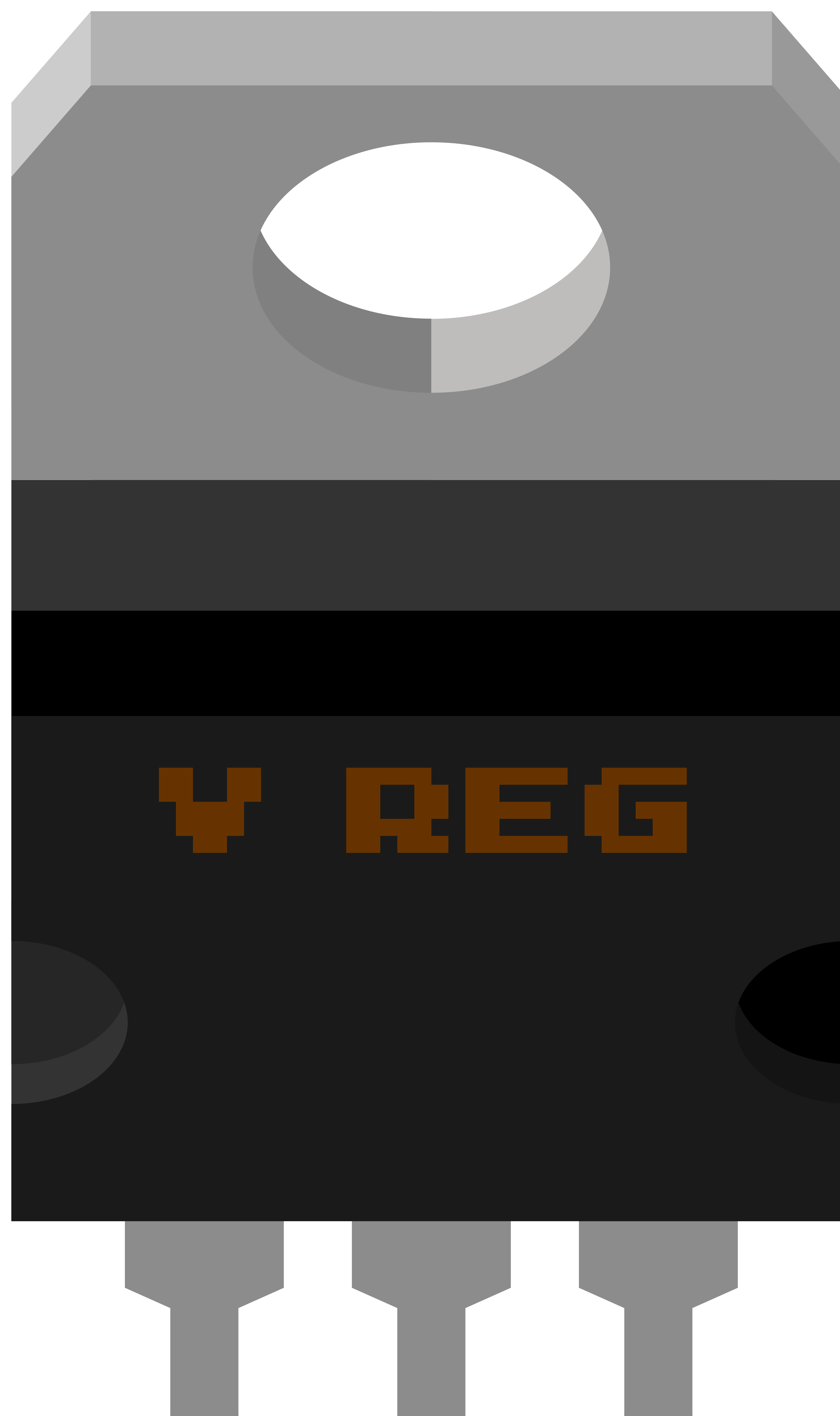
The LM79xx series of voltage regulators are integrated circuits that provide a stable negative voltage output. These negative linear voltage regulators are essential in various electronic applications where a fixed negative voltage is required. They are commonly used in power supplies, instrumentation, and digital systems to ensure that the voltage levels remain within a specific range for the proper operation of electronic devices.

Explore Projects Built with LM79xx Voltage Regulator

Use Cirkit Designer to design, explore, and prototype these projects online. Some projects support real-time simulation. Click "Open Project" to start designing instantly!
Solar-Powered Battery Charging System with XL6009 Voltage Regulator
Image of SISTEMA DE ALIMENTACION Y CARGA SENSORES DS18B20 Y SENSOR DE TURBIDEZ: A project utilizing LM79xx Voltage Regulator in a practical application
This circuit features a solar panel ('Do solara') connected to a voltage regulator ('XL6009 Voltage Regulator') to stabilize the output voltage. The regulated voltage is available at a terminal block ('Terminal PCB 2 Pin') for further use. Additionally, a Li-ion battery ('18650 Li-ion Battery') is connected to the solar panel for charging, with the solar panel's output also routed through the voltage regulator.
Cirkit Designer LogoOpen Project in Cirkit Designer
Battery-Powered LED Control Circuit with Potentiometer and Transistors
Image of STROBE LIGHTS: A project utilizing LM79xx Voltage Regulator in a practical application
This circuit is a regulated power supply with a 12V battery input, a 7805 voltage regulator providing a 5V output, and a potentiometer for adjustable voltage control. It includes transistors and resistors for current regulation and an LED indicator to show the operational status.
Cirkit Designer LogoOpen Project in Cirkit Designer
LM317 Voltage Regulator Circuit for Adjustable Power Supply with Transformer and Diodes
Image of 12V BULB LIGHT DIMMER CIRCUIT: A project utilizing LM79xx Voltage Regulator in a practical application
This circuit is a regulated power supply that converts AC voltage to a stable DC voltage. It uses a transformer to step down the AC voltage, diodes for rectification, an electrolytic capacitor for smoothing, and an LM317 voltage regulator to provide a stable output voltage, which is adjustable via a potentiometer. The output powers a bulb.
Cirkit Designer LogoOpen Project in Cirkit Designer
AC to DC Power Supply with Voltage Regulation and Multimeter Monitoring
Image of Copy of 8 volt AC to DC convertor: A project utilizing LM79xx Voltage Regulator in a practical application
This circuit is a regulated power supply that steps down and converts AC voltage to a stable 8V DC output. It includes a transformer for voltage reduction, a bridge rectifier for AC to DC conversion, a capacitor for voltage smoothing, and a 7808 regulator for voltage stabilization. A multimeter is connected to measure the output voltage.
Cirkit Designer LogoOpen Project in Cirkit Designer

Explore Projects Built with LM79xx Voltage Regulator

Use Cirkit Designer to design, explore, and prototype these projects online. Some projects support real-time simulation. Click "Open Project" to start designing instantly!
Image of SISTEMA DE ALIMENTACION Y CARGA SENSORES DS18B20 Y SENSOR DE TURBIDEZ: A project utilizing LM79xx Voltage Regulator in a practical application
Solar-Powered Battery Charging System with XL6009 Voltage Regulator
This circuit features a solar panel ('Do solara') connected to a voltage regulator ('XL6009 Voltage Regulator') to stabilize the output voltage. The regulated voltage is available at a terminal block ('Terminal PCB 2 Pin') for further use. Additionally, a Li-ion battery ('18650 Li-ion Battery') is connected to the solar panel for charging, with the solar panel's output also routed through the voltage regulator.
Cirkit Designer LogoOpen Project in Cirkit Designer
Image of STROBE LIGHTS: A project utilizing LM79xx Voltage Regulator in a practical application
Battery-Powered LED Control Circuit with Potentiometer and Transistors
This circuit is a regulated power supply with a 12V battery input, a 7805 voltage regulator providing a 5V output, and a potentiometer for adjustable voltage control. It includes transistors and resistors for current regulation and an LED indicator to show the operational status.
Cirkit Designer LogoOpen Project in Cirkit Designer
Image of 12V BULB LIGHT DIMMER CIRCUIT: A project utilizing LM79xx Voltage Regulator in a practical application
LM317 Voltage Regulator Circuit for Adjustable Power Supply with Transformer and Diodes
This circuit is a regulated power supply that converts AC voltage to a stable DC voltage. It uses a transformer to step down the AC voltage, diodes for rectification, an electrolytic capacitor for smoothing, and an LM317 voltage regulator to provide a stable output voltage, which is adjustable via a potentiometer. The output powers a bulb.
Cirkit Designer LogoOpen Project in Cirkit Designer
Image of Copy of 8 volt AC to DC convertor: A project utilizing LM79xx Voltage Regulator in a practical application
AC to DC Power Supply with Voltage Regulation and Multimeter Monitoring
This circuit is a regulated power supply that steps down and converts AC voltage to a stable 8V DC output. It includes a transformer for voltage reduction, a bridge rectifier for AC to DC conversion, a capacitor for voltage smoothing, and a 7808 regulator for voltage stabilization. A multimeter is connected to measure the output voltage.
Cirkit Designer LogoOpen Project in Cirkit Designer

Common Applications and Use Cases

  • Power supplies
  • Audio equipment
  • Motor control circuits
  • Battery chargers
  • Automotive electronics
  • Instrumentation

Technical Specifications

The LM79xx series includes several models, each providing a different fixed output voltage. Below are the key technical details for a generic LM79xx device. Replace "xx" with the specific model number for the exact output voltage (e.g., LM7905 for -5V output).

Key Technical Details

  • Output Voltage: -5V, -12V, -15V (depending on the model)
  • Output Current: Up to 1A
  • Input Voltage (min): Output Voltage - 2V
  • Input Voltage (max): -35V
  • Quiescent Current: 5mA (typical)
  • Load Regulation: 0.2% (typical)
  • Line Regulation: 0.01% / V (typical)
  • Thermal Overload Protection
  • Short Circuit Protection

Pin Configuration and Descriptions

Pin Number Name Description
1 Input The input pin where the unregulated negative voltage is applied.
2 Ground The ground pin, which is typically connected to the system ground.
3 Output The output pin that provides the regulated negative voltage.

Usage Instructions

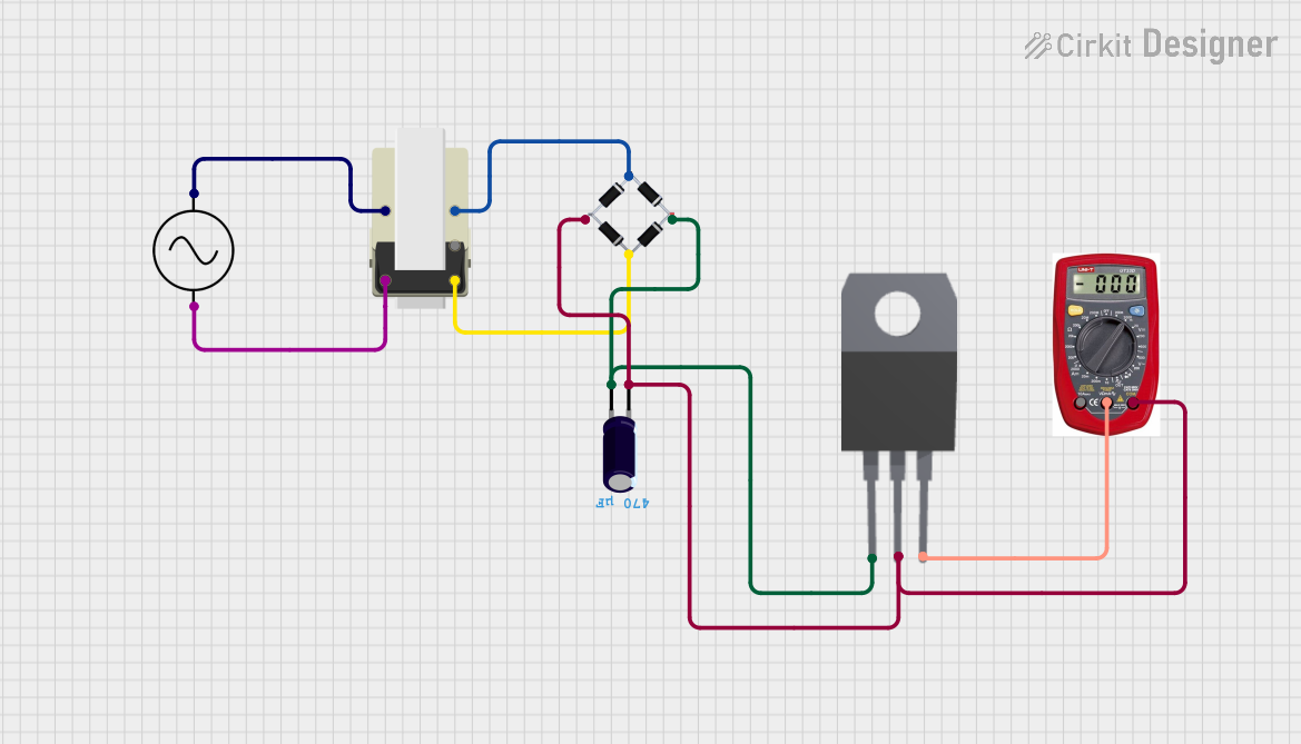
How to Use the LM79xx in a Circuit

  1. Connect the unregulated negative voltage to the Input pin (Pin 1).
  2. Connect the Ground pin (Pin 2) to the system ground.
  3. The Output pin (Pin 3) will provide the regulated negative voltage.
  4. Place a capacitor (typically 1µF or greater) between the Input pin and Ground to improve ripple rejection.
  5. Place a capacitor (typically 1µF or greater) between the Output pin and Ground to stabilize the output voltage.

Important Considerations and Best Practices

  • Ensure that the input voltage is at least 2V greater than the desired output voltage but does not exceed the maximum input voltage rating.
  • The capacitors on the input and output should be close to the regulator to minimize noise and oscillations.
  • Avoid exceeding the maximum current rating of the regulator to prevent thermal shutdown or damage.
  • Use a heat sink if the power dissipation is expected to be high due to a large voltage difference between input and output or high output current.

Troubleshooting and FAQs

Common Issues

  • Voltage Output is Too Low or Unstable: Check the input voltage and capacitors. Ensure that the input voltage is sufficient and the capacitors are not damaged.
  • Regulator Overheating: This may be due to excessive power dissipation. Check the input-to-output voltage difference and the current draw. Use a heat sink if necessary.
  • No Output Voltage: Ensure that the regulator is correctly oriented and that the input voltage is present. Check for short circuits or an improperly connected ground.

Solutions and Tips

  • Always verify the polarity of the input voltage and the orientation of the regulator.
  • Use capacitors with low equivalent series resistance (ESR) for better performance.
  • If the regulator does not start, increase the value of the output capacitor.

FAQs

Q: Can I use the LM79xx without capacitors? A: It is not recommended to use the LM79xx without capacitors as they help to stabilize the output voltage and reduce noise.

Q: What is the maximum current the LM79xx can handle? A: The LM79xx can typically handle up to 1A of output current. Consult the datasheet for the specific model you are using.

Q: How do I choose a heat sink for the LM79xx? A: The heat sink size depends on the power dissipation, which is the product of the voltage difference between input and output and the output current. Use a heat sink with appropriate thermal resistance to keep the regulator temperature within safe limits.

Q: Can the LM79xx series regulators be paralleled for more current? A: Paralleling linear regulators is generally not recommended due to the potential for uneven current sharing and thermal imbalance.

Example Connection to an Arduino UNO

The LM79xx is not typically used with an Arduino UNO directly, as the Arduino operates on positive voltage levels. However, if a negative voltage is required for other parts of the project, the LM79xx can be included in the circuit. No specific code is needed for the regulator itself, as it operates independently of the microcontroller.

// No specific code is required for the LM79xx voltage regulator.
// It functions independently of the microcontroller and does not require control via software.

Remember to ensure that any negative voltages generated are not inadvertently connected to the Arduino's ground or any I/O pins, as this could damage the microcontroller.