
How to Use PC817: Examples, Pinouts, and Specs
 Design with PC817 in Cirkit Designer
Introduction
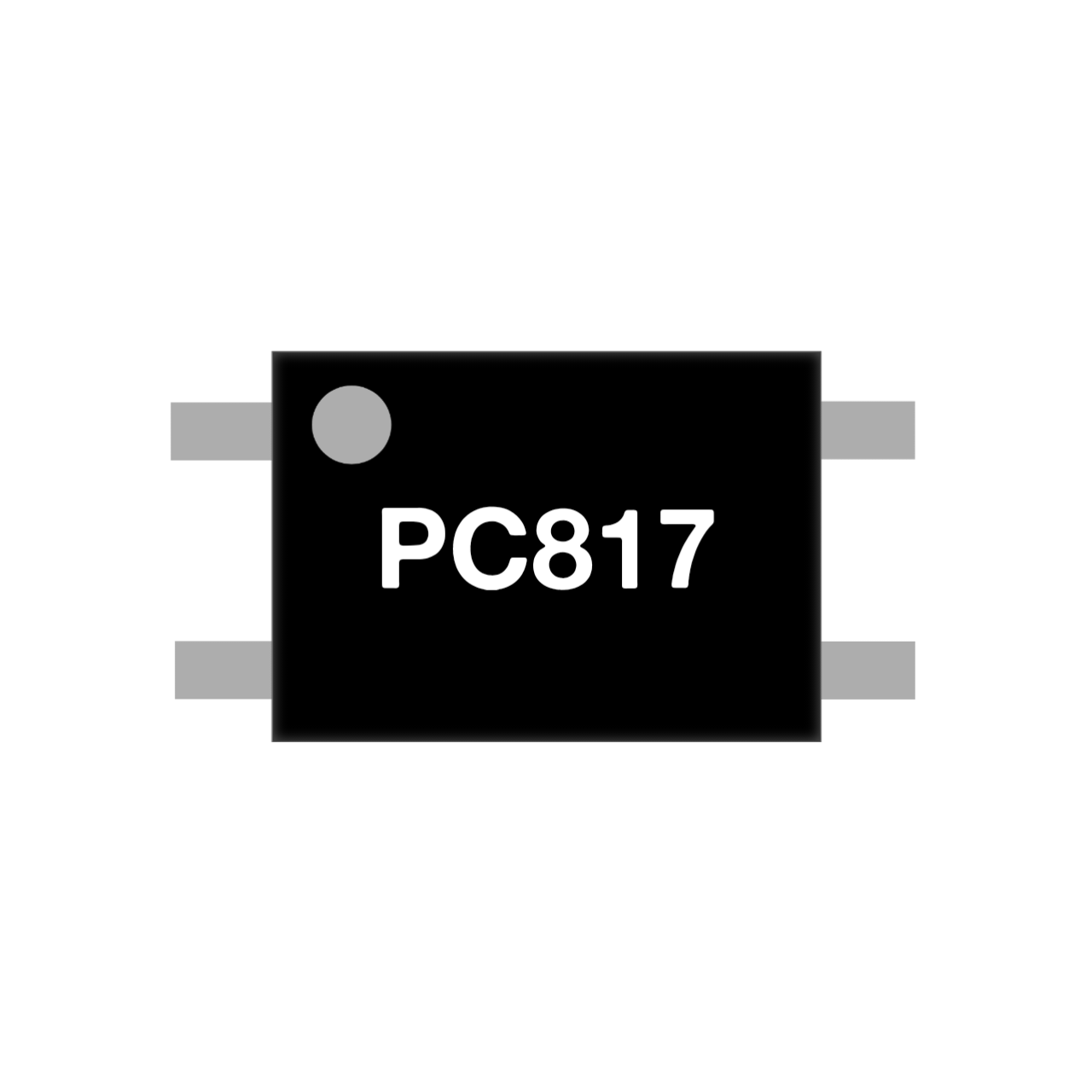
The PC817 is an optocoupler manufactured by SKR Electronics Lab. It integrates a light-emitting diode (LED) and a phototransistor within a single compact package. This component is widely used for electrical isolation between different sections of a circuit, ensuring signal transmission while protecting sensitive components from high voltages, surges, and electrical noise.
Explore Projects Built with PC817
 Open Project in Cirkit Designer
 Open Project in Cirkit Designer
 Open Project in Cirkit Designer
 Open Project in Cirkit Designer
Explore Projects Built with PC817
Open Project in Cirkit DesignerOpen Project in Cirkit DesignerOpen Project in Cirkit DesignerOpen Project in Cirkit DesignerCommon Applications and Use Cases
- Isolation between high-voltage and low-voltage circuits
- Signal transmission in noisy environments
- Microcontroller interfacing with high-power devices
- Switching power supplies
- Motor control circuits
- Industrial automation systems
Technical Specifications
Below are the key technical details of the PC817 optocoupler:
| Parameter | Value |
|---|---|
| Manufacturer | SKR Electronics Lab |
| Part ID | PC817 |
| Input Forward Voltage (VF) | 1.2V (typical), 1.4V (maximum) |
| Input Forward Current (IF) | 20mA (typical), 50mA (maximum) |
| Output Collector-Emitter Voltage (VCEO) | 35V (maximum) |
| Output Collector Current (IC) | 50mA (maximum) |
| Isolation Voltage | 5000Vrms |
| Current Transfer Ratio (CTR) | 50% to 600% (depending on model) |
| Operating Temperature Range | -30°C to +100°C |
| Package Type | 4-pin DIP |
Pin Configuration and Descriptions
The PC817 has a 4-pin configuration, as detailed in the table below:
| Pin Number | Name | Description |
|---|---|---|
| 1 | Anode (A) | Positive terminal of the internal LED |
| 2 | Cathode (K) | Negative terminal of the internal LED |
| 3 | Emitter (E) | Emitter terminal of the phototransistor |
| 4 | Collector (C) | Collector terminal of the phototransistor |
Usage Instructions
How to Use the PC817 in a Circuit
Connect the LED Side (Input):
- Connect the anode (Pin 1) to the positive side of the input signal through a current-limiting resistor.
- Connect the cathode (Pin 2) to the ground of the input circuit.
Connect the Phototransistor Side (Output):
- Connect the collector (Pin 4) to the positive voltage supply of the output circuit through a pull-up resistor.
- Connect the emitter (Pin 3) to the ground of the output circuit.
Choose a Suitable Resistor:
- Calculate the current-limiting resistor for the LED using Ohm's Law: [ R = \frac{V_{in} - V_F}{I_F} ] where ( V_{in} ) is the input voltage, ( V_F ) is the forward voltage of the LED (1.2V typical), and ( I_F ) is the desired forward current (e.g., 10mA).
Verify Isolation:
- Ensure that the input and output circuits share no direct electrical connection to maintain isolation.
Important Considerations and Best Practices
- Current Transfer Ratio (CTR): Ensure the CTR of the PC817 meets the requirements of your application. A higher CTR indicates better signal transfer efficiency.
- Input Current: Avoid exceeding the maximum forward current (50mA) to prevent damage to the internal LED.
- Output Voltage: Ensure the collector-emitter voltage does not exceed 35V.
- Temperature: Operate the PC817 within the specified temperature range (-30°C to +100°C) to ensure reliable performance.
Example: Interfacing PC817 with Arduino UNO
Below is an example of how to use the PC817 to interface a 5V Arduino UNO with a 12V relay module:
Circuit Connections
- Input Side:
- Connect Pin 1 (Anode) to Arduino digital pin 7 through a 220Ω resistor.
- Connect Pin 2 (Cathode) to Arduino GND.
- Output Side:
- Connect Pin 4 (Collector) to the 12V relay module input.
- Connect Pin 3 (Emitter) to the GND of the 12V power supply.
Arduino Code
// PC817 Optocoupler Example with Arduino UNO
// This code toggles the optocoupler to control a 12V relay module.

const int optoPin = 7; // Arduino pin connected to PC817 anode (through resistor)

void setup() {
  pinMode(optoPin, OUTPUT); // Set optoPin as an output
}

void loop() {
  digitalWrite(optoPin, HIGH); // Turn on the optocoupler LED
  delay(1000);                // Wait for 1 second
  digitalWrite(optoPin, LOW);  // Turn off the optocoupler LED
  delay(1000);                // Wait for 1 second
}
Troubleshooting and FAQs
Common Issues and Solutions
No Output Signal:
- Cause: Incorrect resistor value on the input side.
- Solution: Recalculate the resistor value to ensure proper current flow through the LED.
Output Signal is Weak or Unstable:
- Cause: Insufficient pull-up resistor on the output side.
- Solution: Use a pull-up resistor with a value between 1kΩ and 10kΩ, depending on the circuit requirements.
Component Overheating:
- Cause: Exceeding the maximum input current or output voltage.
- Solution: Verify that the input current is below 50mA and the output voltage is below 35V.
No Isolation Between Circuits:
- Cause: Improper wiring or shared ground between input and output circuits.
- Solution: Ensure complete electrical isolation between the input and output sides.
FAQs
Q1: Can the PC817 handle AC signals?
A1: Yes, the PC817 can handle AC signals on the input side, but you must use a rectifier circuit to convert the AC signal to DC for proper operation.
Q2: What is the typical lifespan of the PC817?
A2: The PC817 has a long operational lifespan when used within its specified ratings, typically exceeding 100,000 hours.
Q3: Can I use the PC817 for high-speed signal transmission?
A3: The PC817 is suitable for low- to medium-speed applications. For high-speed signals, consider using optocouplers designed for faster response times.
Q4: Is the PC817 suitable for switching high-power loads?
A4: No, the PC817 is designed for low-power signal isolation. Use a relay or power transistor for high-power switching applications.