How to Use Controllino Mini: Examples, Pinouts, and Specs
Introduction
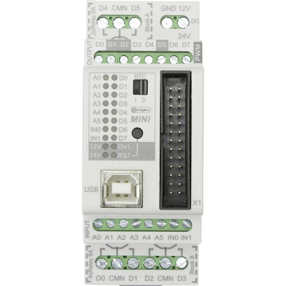
The Controllino Mini is a compact, Arduino-based programmable logic controller (PLC) designed for automation and control applications. Manufactured by Controllino, this versatile device combines the flexibility of Arduino programming with the robustness of industrial-grade hardware. It features a range of digital and analog inputs/outputs, making it ideal for projects in home automation, industrial control, robotics, and more.
Explore Projects Built with Controllino Mini

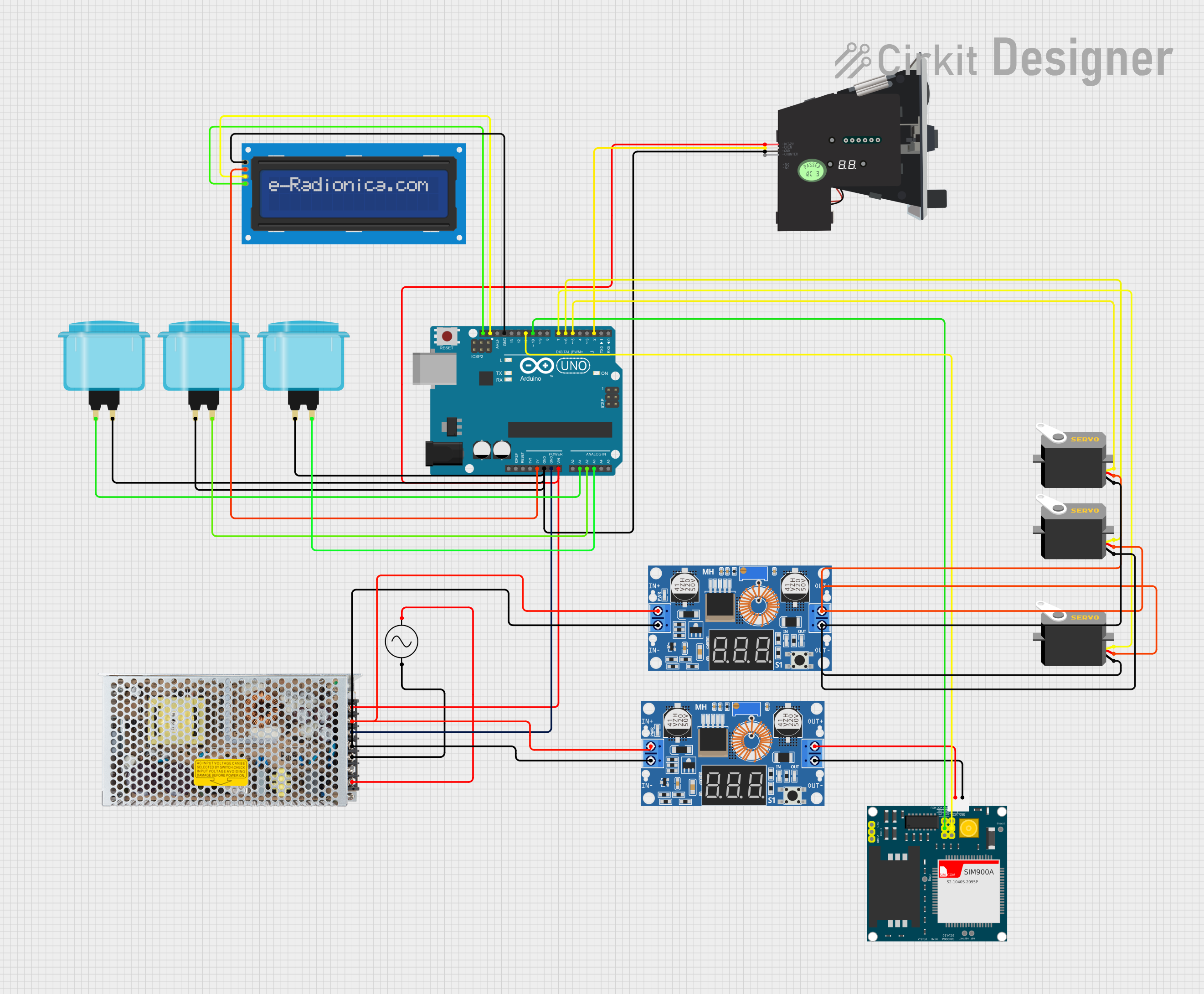

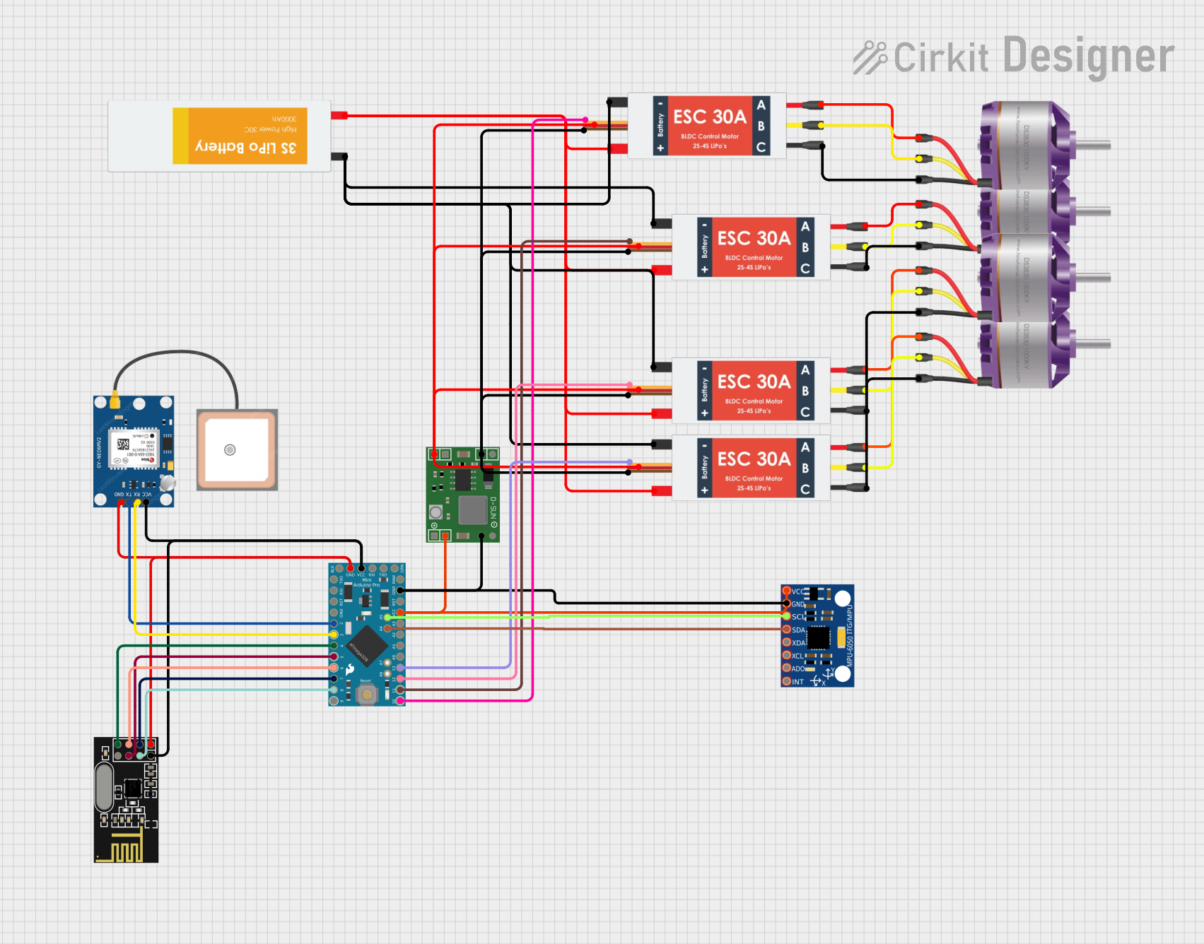
Explore Projects Built with Controllino Mini
Common Applications
- Home automation systems (e.g., lighting, HVAC control)
- Industrial machinery control
- Robotics and mechatronics
- IoT (Internet of Things) applications
- Educational and prototyping projects
Technical Specifications
Key Technical Details
| Parameter | Specification |
|---|---|
| Microcontroller | ATmega328P (Arduino-compatible) |
| Operating Voltage | 5V DC |
| Input Voltage Range | 12-24V DC |
| Digital Inputs | 6 opto-isolated inputs |
| Digital Outputs | 6 relay outputs (230V AC / 6A max per relay) |
| Analog Inputs | 4 (0-10V DC) |
| Communication Interfaces | UART, I2C, SPI |
| Programming Interface | USB (via Arduino IDE) |
| Dimensions | 72mm x 90mm x 58mm |
| Certifications | CE, UL |
Pin Configuration and Descriptions
Digital Inputs
| Pin | Description | Voltage Range |
|---|---|---|
| DI1 | Digital Input 1 | 12-24V DC |
| DI2 | Digital Input 2 | 12-24V DC |
| DI3 | Digital Input 3 | 12-24V DC |
| DI4 | Digital Input 4 | 12-24V DC |
| DI5 | Digital Input 5 | 12-24V DC |
| DI6 | Digital Input 6 | 12-24V DC |
Digital Outputs (Relays)
| Pin | Description | Max Voltage/Current |
|---|---|---|
| DO1 | Digital Output 1 (Relay) | 230V AC / 6A |
| DO2 | Digital Output 2 (Relay) | 230V AC / 6A |
| DO3 | Digital Output 3 (Relay) | 230V AC / 6A |
| DO4 | Digital Output 4 (Relay) | 230V AC / 6A |
| DO5 | Digital Output 5 (Relay) | 230V AC / 6A |
| DO6 | Digital Output 6 (Relay) | 230V AC / 6A |
Analog Inputs
| Pin | Description | Voltage Range |
|---|---|---|
| AI1 | Analog Input 1 | 0-10V DC |
| AI2 | Analog Input 2 | 0-10V DC |
| AI3 | Analog Input 3 | 0-10V DC |
| AI4 | Analog Input 4 | 0-10V DC |
Usage Instructions
How to Use the Controllino Mini in a Circuit
- Power Supply: Connect a 12-24V DC power supply to the Controllino Mini's power input terminals.
- Digital Inputs: Connect sensors or switches to the digital input pins (DI1-DI6). Ensure the input voltage is within the 12-24V DC range.
- Digital Outputs: Use the relay outputs (DO1-DO6) to control external devices such as lights, motors, or solenoids. Ensure the load does not exceed 230V AC / 6A per relay.
- Analog Inputs: Connect analog sensors (e.g., temperature or pressure sensors) to the analog input pins (AI1-AI4). The input voltage should be within the 0-10V DC range.
- Programming: Use the Arduino IDE to write and upload code to the Controllino Mini via the USB interface. Select "Arduino Uno" as the board type in the IDE.
Important Considerations and Best Practices
- Isolation: The digital inputs are opto-isolated for safety. Ensure proper grounding to avoid noise interference.
- Relay Ratings: Do not exceed the maximum voltage and current ratings of the relays to prevent damage.
- Analog Input Range: Ensure that the analog input voltage does not exceed 10V DC to avoid damaging the microcontroller.
- Programming: Always double-check your code for errors before uploading to prevent unintended behavior.
- Environment: Operate the Controllino Mini in a dry, dust-free environment within the specified temperature range.
Example Code for Arduino UNO
Below is an example code snippet to toggle a relay output (DO1) based on a digital input (DI1):
// Define pin numbers for digital input and output
const int digitalInputPin = 2;  // DI1 is connected to pin 2
const int relayOutputPin = 3;   // DO1 is connected to pin 3

void setup() {
  pinMode(digitalInputPin, INPUT);  // Set DI1 as input
  pinMode(relayOutputPin, OUTPUT); // Set DO1 as output
  digitalWrite(relayOutputPin, LOW); // Ensure relay is off initially
}

void loop() {
  int inputState = digitalRead(digitalInputPin); // Read the state of DI1

  if (inputState == HIGH) {
    digitalWrite(relayOutputPin, HIGH); // Turn on the relay if DI1 is HIGH
  } else {
    digitalWrite(relayOutputPin, LOW);  // Turn off the relay if DI1 is LOW
  }
}
Troubleshooting and FAQs
Common Issues and Solutions
Problem: The Controllino Mini does not power on.
- Solution: Verify that the power supply is connected properly and provides 12-24V DC. Check for loose connections.
Problem: Digital inputs are not responding.
- Solution: Ensure the input voltage is within the 12-24V DC range. Check the wiring and grounding.
Problem: Relays are not switching.
- Solution: Verify that the relay output is not overloaded. Check the code logic and ensure the correct pins are used.
Problem: Analog inputs are giving incorrect readings.
- Solution: Ensure the input voltage is within the 0-10V DC range. Use a multimeter to verify the sensor output.
Problem: Unable to upload code via Arduino IDE.
- Solution: Ensure the correct board type ("Arduino Uno") and COM port are selected in the IDE. Check the USB connection.
FAQs
Q: Can the Controllino Mini be used with other Arduino libraries?
- A: Yes, the Controllino Mini is fully compatible with most Arduino libraries.
Q: Is the Controllino Mini suitable for industrial environments?
- A: Yes, it is designed for industrial use and complies with CE and UL certifications.
Q: Can I use the Controllino Mini for IoT applications?
- A: Yes, you can integrate it with IoT platforms using communication interfaces like UART, I2C, or SPI.
Q: What is the maximum current the relays can handle?
- A: Each relay can handle up to 6A at 230V AC.
Q: Does the Controllino Mini support PWM outputs?
- A: Yes, PWM functionality is available on specific pins, as it is based on the ATmega328P microcontroller.