How to Use Mini 5V Buck Conveter: Examples, Pinouts, and Specs
Introduction
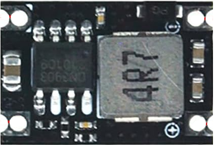
The Mini 5V Buck Converter (MP1584EN) is a compact and efficient DC-DC step-down voltage regulator designed to convert a higher input voltage to a stable 5V output. Manufactured by Generic, this module is widely used in applications requiring efficient power delivery to low-voltage devices. Its small size and high efficiency make it ideal for powering microcontrollers, sensors, and other low-power electronic components.
Explore Projects Built with Mini 5V Buck Conveter


Explore Projects Built with Mini 5V Buck Conveter
Common Applications
- Powering microcontrollers (e.g., Arduino, ESP32, Raspberry Pi)
- Battery-powered devices
- Robotics and IoT projects
- LED drivers
- General-purpose voltage regulation in electronic circuits
Technical Specifications
Below are the key technical details of the Mini 5V Buck Converter:
| Parameter | Value |
|---|---|
| Input Voltage Range | 4.5V to 28V |
| Output Voltage | Adjustable (default: 5V) |
| Output Current | Up to 3A (with proper heat dissipation) |
| Efficiency | Up to 92% |
| Switching Frequency | 340 kHz |
| Operating Temperature | -40°C to +85°C |
| Dimensions | 22mm x 17mm x 4mm |
Pin Configuration and Descriptions
The Mini 5V Buck Converter has four main pins for input and output connections:
| Pin Name | Description |
|---|---|
| VIN | Input voltage pin (connect to 4.5V–28V power source) |
| GND | Ground pin (common ground for input and output) |
| VOUT | Regulated output voltage pin (default: 5V) |
| ADJ | Voltage adjustment pin (optional, for custom output voltage) |
Usage Instructions
How to Use the Mini 5V Buck Converter in a Circuit
Connect the Input Voltage:
- Attach the VIN pin to the positive terminal of your power source (4.5V–28V).
- Connect the GND pin to the ground of your power source.
Connect the Output Voltage:
- Attach the VOUT pin to the positive terminal of the load (e.g., microcontroller, sensor).
- Ensure the load's ground is connected to the GND pin.
Adjust the Output Voltage (Optional):
- If a voltage other than 5V is required, use a small screwdriver to turn the onboard potentiometer clockwise (to increase voltage) or counterclockwise (to decrease voltage).
- Use a multimeter to measure the output voltage while adjusting.
Verify Connections:
- Double-check all connections to ensure proper polarity and avoid short circuits.
Power On:
- Turn on the power source and verify the output voltage using a multimeter.
Important Considerations and Best Practices
- Heat Dissipation: For currents above 1.5A, ensure proper heat dissipation by adding a heatsink or improving airflow around the module.
- Input Voltage Range: Do not exceed the maximum input voltage of 28V to avoid damaging the module.
- Load Requirements: Ensure the connected load does not exceed the module's maximum current rating of 3A.
- Voltage Adjustment: When adjusting the output voltage, disconnect the load to prevent accidental overvoltage damage.
Example: Using the Mini 5V Buck Converter with an Arduino UNO
Below is an example of how to use the Mini 5V Buck Converter to power an Arduino UNO from a 12V power source:
Circuit Diagram
- Connect the VIN pin of the buck converter to the positive terminal of the 12V power source.
- Connect the GND pin of the buck converter to the ground of the power source.
- Connect the VOUT pin of the buck converter to the 5V pin of the Arduino UNO.
- Connect the GND pin of the buck converter to the GND pin of the Arduino UNO.
Arduino Code Example
// Example code to blink an LED connected to pin 13 of the Arduino UNO
// Ensure the Arduino is powered via the Mini 5V Buck Converter

void setup() {
  pinMode(13, OUTPUT); // Set pin 13 as an output
}

void loop() {
  digitalWrite(13, HIGH); // Turn the LED on
  delay(1000);            // Wait for 1 second
  digitalWrite(13, LOW);  // Turn the LED off
  delay(1000);            // Wait for 1 second
}
Troubleshooting and FAQs
Common Issues and Solutions
| Issue | Possible Cause | Solution |
|---|---|---|
| No output voltage | Incorrect wiring or loose connections | Verify all connections and ensure proper polarity. |
| Output voltage is unstable | Input voltage is too low or noisy | Ensure the input voltage is within the specified range and use a capacitor to filter noise. |
| Module overheats during operation | Excessive current draw or poor heat dissipation | Reduce the load current or add a heatsink to the module. |
| Cannot adjust output voltage | Potentiometer is damaged or improperly adjusted | Replace the potentiometer or adjust it carefully with a screwdriver. |
FAQs
Can I use the Mini 5V Buck Converter to power a Raspberry Pi?
- Yes, but ensure the current draw of the Raspberry Pi (including peripherals) does not exceed 3A.
What happens if I exceed the input voltage range?
- Exceeding the maximum input voltage of 28V can permanently damage the module.
Can I use this module to step down voltage to levels other than 5V?
- Yes, the output voltage is adjustable using the onboard potentiometer. However, ensure the output voltage is within the load's operating range.
Is the module protected against short circuits?
- The MP1584EN chip includes basic protection features, but it is recommended to avoid short circuits to prevent damage.
By following this documentation, you can effectively integrate the Mini 5V Buck Converter into your projects for efficient and reliable power regulation.