How to Use LDR: Examples, Pinouts, and Specs
Introduction
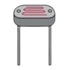
A Light Dependent Resistor (LDR), also known as a photoresistor, is a passive electronic component whose resistance decreases as the intensity of incident light increases. This property makes it an ideal choice for light sensing and control applications. LDRs are widely used in devices such as automatic streetlights, light meters, and alarm systems.
Explore Projects Built with LDR
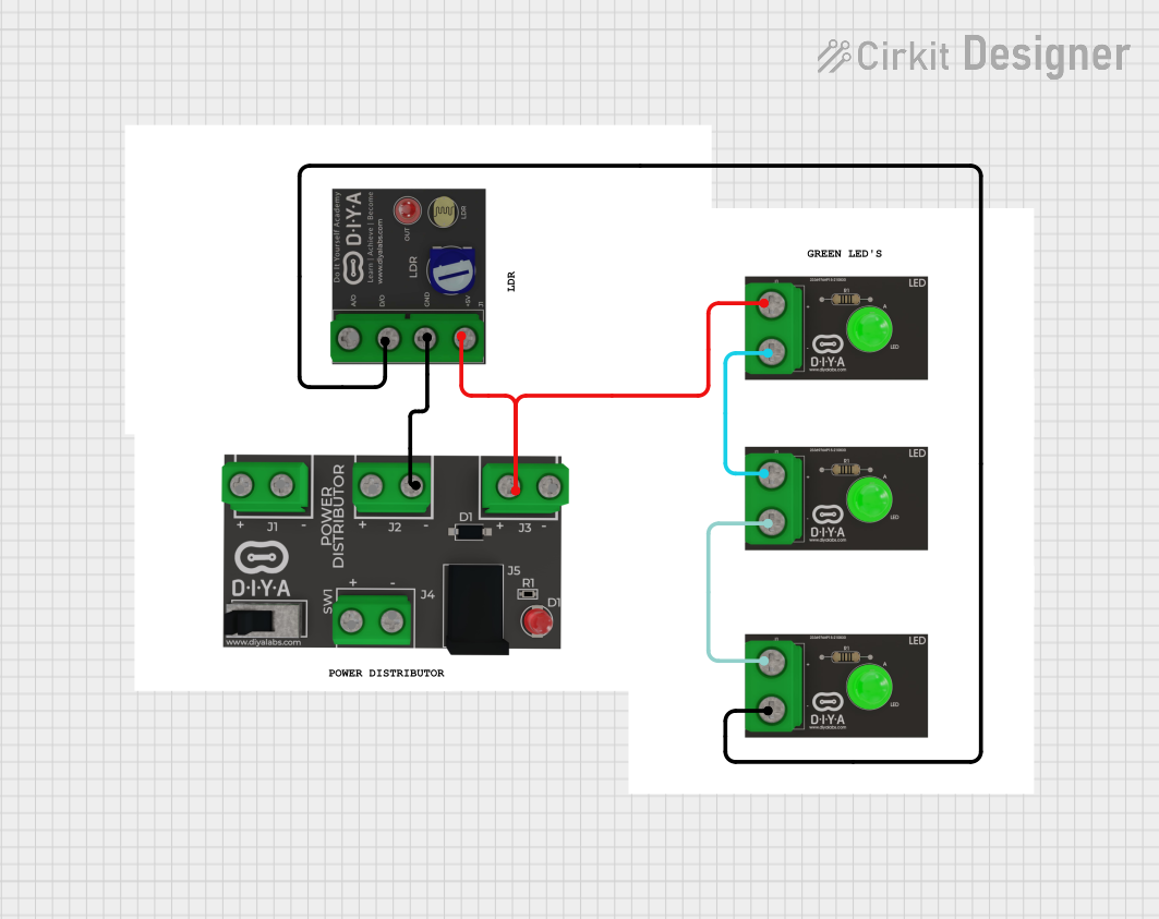
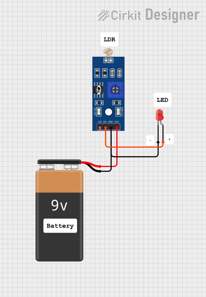
Explore Projects Built with LDR
Common Applications:
- Automatic lighting systems (e.g., streetlights)
- Light intensity measurement
- Alarm systems triggered by light changes
- Solar tracking systems
- Electronic toys and gadgets
Technical Specifications
Below are the key technical details for the LDR manufactured by ARDUINO, part ID: UNO.
General Specifications:
- Resistance in Darkness: Typically 1 MΩ or higher
- Resistance in Bright Light: Typically 1 kΩ or lower
- Spectral Response: 400 nm to 700 nm (visible light range)
- Maximum Voltage: 150 V (varies by model)
- Power Dissipation: 100 mW (typical)
- Response Time: Rise time ~10 ms, fall time ~30 ms
Pin Configuration:
The LDR is a two-terminal device with no polarity. Below is the pin description:
| Pin Name | Description |
|---|---|
| Pin 1 | Connects to one side of the circuit |
| Pin 2 | Connects to the other side of the circuit |
Usage Instructions
How to Use the LDR in a Circuit:
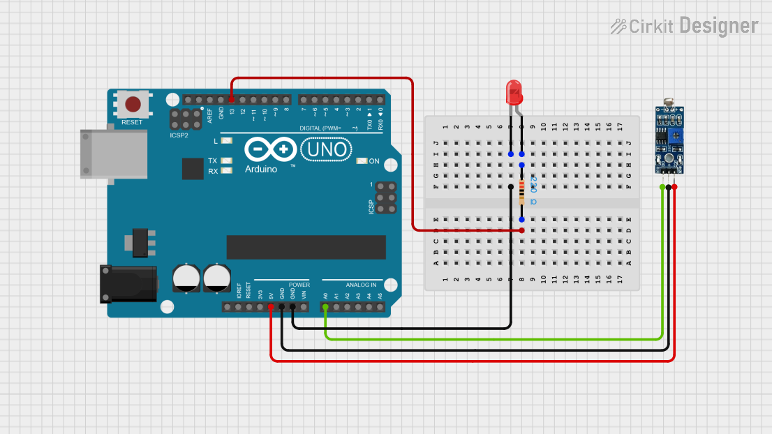
Basic Circuit Setup:
- Connect one terminal of the LDR to a voltage source (e.g., 5V).
- Connect the other terminal to a resistor (commonly 10 kΩ) in series, forming a voltage divider.
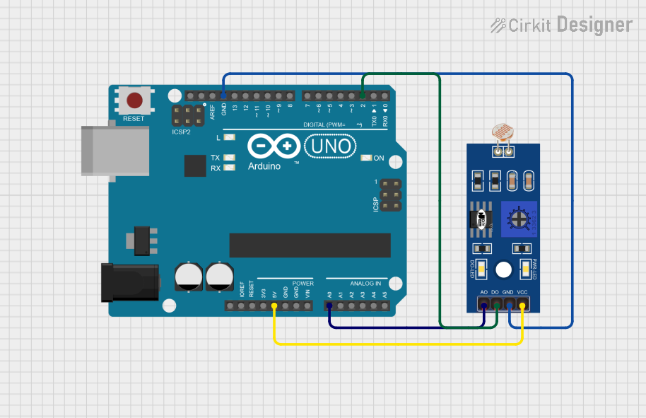
- The junction between the LDR and the resistor can be connected to an analog input pin of a microcontroller (e.g., Arduino UNO) to measure the voltage.
Voltage Divider Formula: The output voltage at the junction can be calculated using the formula: [ V_{out} = V_{in} \times \frac{R_{LDR}}{R_{LDR} + R_{fixed}} ] where ( R_{LDR} ) is the resistance of the LDR and ( R_{fixed} ) is the fixed resistor.
Arduino UNO Example Code: Below is an example of how to use the LDR with an Arduino UNO to measure light intensity:
// Define the analog pin connected to the LDR
const int ldrPin = A0;

void setup() {
  Serial.begin(9600); // Initialize serial communication at 9600 baud
}

void loop() {
  int ldrValue = analogRead(ldrPin); // Read the analog value from the LDR

  // Convert the analog value to a voltage (assuming 5V reference)
  float voltage = ldrValue * (5.0 / 1023.0);

  // Print the LDR value and voltage to the Serial Monitor
  Serial.print("LDR Value: ");
  Serial.print(ldrValue);
  Serial.print(" | Voltage: ");
  Serial.println(voltage);

  delay(500); // Wait for 500 ms before the next reading
}
Important Considerations:
- Light Sensitivity: The LDR is sensitive to visible light. Ensure it is not exposed to infrared or ultraviolet light unless specified.
- Temperature Effects: The resistance of the LDR may vary slightly with temperature changes.
- Response Time: LDRs have a slower response time compared to photodiodes or phototransistors, making them unsuitable for high-speed applications.
Troubleshooting and FAQs
Common Issues:
No Change in Output Voltage:
- Cause: Incorrect wiring or a damaged LDR.
- Solution: Verify the connections and ensure the LDR is functional by testing its resistance with a multimeter.
Inconsistent Readings:
- Cause: Ambient light interference or unstable power supply.
- Solution: Shield the LDR from unwanted light sources and use a stable power supply.
Low Sensitivity:
- Cause: Incorrect resistor value in the voltage divider.
- Solution: Experiment with different resistor values (e.g., 1 kΩ to 100 kΩ) to optimize sensitivity.
FAQs:
Can the LDR detect infrared light?
- No, standard LDRs are designed to respond to visible light (400 nm to 700 nm). Specialized sensors are required for infrared detection.
What is the maximum distance for light detection?
- The detection range depends on the intensity of the light source. Stronger light sources can be detected from greater distances.
Can I use the LDR with a 3.3V system?
- Yes, the LDR can be used with a 3.3V system. Ensure the voltage divider circuit is adjusted accordingly.
By following this documentation, users can effectively integrate the LDR into their projects and troubleshoot common issues.