How to Use 433 MHz RF Transmitter: Examples, Pinouts, and Specs
Introduction
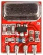
The 433 MHz RF Transmitter is a compact and cost-effective device designed to transmit radio frequency signals at 433 MHz. It is widely used in wireless communication systems, including remote controls, wireless sensor networks, home automation, and other short-range communication applications. This transmitter module is ideal for projects requiring low-power, unlicensed communication over moderate distances.
Explore Projects Built with 433 MHz RF Transmitter


Explore Projects Built with 433 MHz RF Transmitter
Technical Specifications
- Frequency: 433 MHz
- Operating Voltage: 3.3V to 12V DC (typical: 5V)
- Operating Current: 10 mA (typical)
- Transmission Range: Up to 100 meters (line of sight, depending on antenna and environment)
- Modulation Type: Amplitude Shift Keying (ASK)
- Data Rate: Up to 10 kbps
- Antenna: External wire antenna (recommended length: ~17 cm for 433 MHz)
Pin Configuration and Descriptions
| Pin Number | Pin Name | Description |
|---|---|---|
| 1 | VCC | Power supply input (3.3V to 12V DC). Typically connected to 5V. |
| 2 | DATA | Data input pin. Connect to the microcontroller or encoder IC for data input. |
| 3 | GND | Ground pin. Connect to the ground of the power supply and circuit. |
Usage Instructions
How to Use the 433 MHz RF Transmitter in a Circuit
- Power Supply: Connect the VCC pin to a stable DC power source (3.3V to 12V, typically 5V). Ensure the GND pin is connected to the circuit's ground.
- Data Input: Connect the DATA pin to the data output of a microcontroller (e.g., Arduino) or an encoder IC. The transmitter will modulate the input signal and transmit it wirelessly.
- Antenna: Attach a wire antenna (~17 cm for 433 MHz) to the designated antenna pad or solder point on the module. This improves the transmission range and signal quality.
- Pairing with Receiver: Use a compatible 433 MHz RF Receiver module to decode the transmitted signal.
Important Considerations and Best Practices
- Antenna Placement: Ensure the antenna is placed away from metal objects and other sources of interference for optimal performance.
- Power Supply: Use a stable and noise-free power supply to avoid signal distortion.
- Data Encoding: For reliable communication, use an encoder IC (e.g., HT12E) or software-based encoding to format the data before transmission.
- Environment: The transmission range may vary depending on environmental factors such as obstacles, interference, and weather conditions.
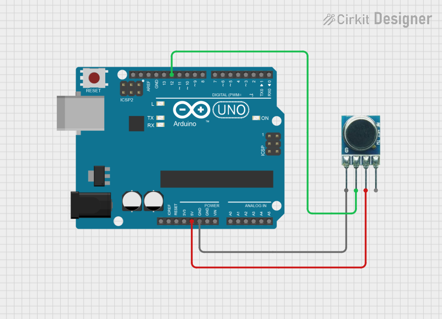
Example: Connecting to an Arduino UNO
Below is an example of how to use the 433 MHz RF Transmitter with an Arduino UNO to send a simple signal.
Circuit Connections
- Connect the VCC pin of the transmitter to the 5V pin on the Arduino.
- Connect the GND pin of the transmitter to the GND pin on the Arduino.
- Connect the DATA pin of the transmitter to digital pin 12 on the Arduino.
Arduino Code Example
// Example code to send a signal using the 433 MHz RF Transmitter
// Requires the RadioHead library for ASK modulation
#include <RH_ASK.h>
#include <SPI.h> // Not used directly, but required for RadioHead library

RH_ASK rf_driver;

void setup() {
  // Initialize the RF driver
  if (!rf_driver.init()) {
    Serial.begin(9600);
    Serial.println("RF Driver initialization failed!");
    while (1); // Halt execution if initialization fails
  }
  Serial.begin(9600);
  Serial.println("RF Transmitter ready.");
}

void loop() {
  const char *message = "Hello, World!"; // Message to transmit
  rf_driver.send((uint8_t *)message, strlen(message)); // Send the message
  rf_driver.waitPacketSent(); // Wait for the message to be sent
  delay(1000); // Wait 1 second before sending the next message
}
Troubleshooting and FAQs
Common Issues and Solutions
No Signal Received by the Receiver
- Ensure the transmitter and receiver are operating at the same frequency (433 MHz).
- Check the antenna connection and placement.
- Verify that the DATA pin is receiving a valid signal from the microcontroller or encoder IC.
Short Transmission Range
- Use a properly sized wire antenna (~17 cm for 433 MHz).
- Minimize obstacles and interference between the transmitter and receiver.
- Increase the operating voltage (up to 12V) for higher transmission power.
Signal Distortion or Noise
- Use a stable power supply with minimal noise.
- Avoid placing the transmitter near high-frequency devices or metal objects.
FAQs
Q: Can I use the 433 MHz RF Transmitter without an antenna?
A: While the transmitter may work without an antenna, the range and signal quality will be significantly reduced. It is highly recommended to use a wire antenna of approximately 17 cm for optimal performance.
Q: What is the maximum range of the 433 MHz RF Transmitter?
A: The maximum range is up to 100 meters in line-of-sight conditions. However, obstacles, interference, and environmental factors can reduce the effective range.
Q: Can I use multiple transmitters in the same area?
A: Yes, but ensure that each transmitter uses a unique data encoding scheme to avoid interference and data collisions.
Q: Is the 433 MHz RF Transmitter compatible with other frequencies?
A: No, this module is specifically designed to operate at 433 MHz. For other frequencies, use a transmitter designed for that specific frequency.