How to Use TPL0501 Digital Potentiometer (SPI): Examples, Pinouts, and Specs
Introduction
The TPL0501 is a digital potentiometer manufactured by Texas Instruments (TI). It features a single-channel, 256-tap resistor network that can be controlled via the Serial Peripheral Interface (SPI). This component is ideal for applications requiring precise resistance adjustments, such as volume control, signal conditioning, and sensor calibration. Its compact design and digital control make it a versatile choice for modern electronic systems.
Explore Projects Built with TPL0501 Digital Potentiometer (SPI)


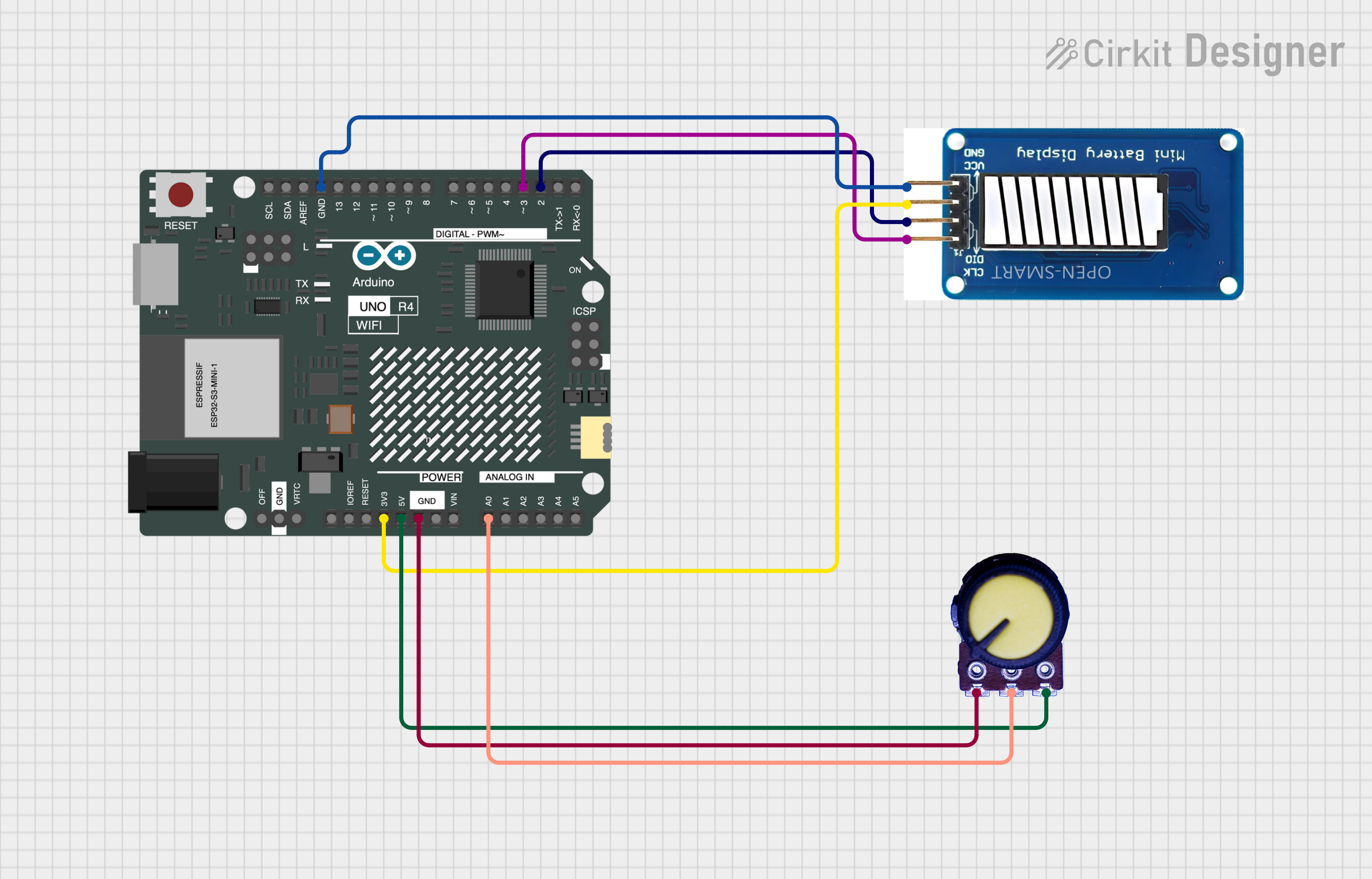
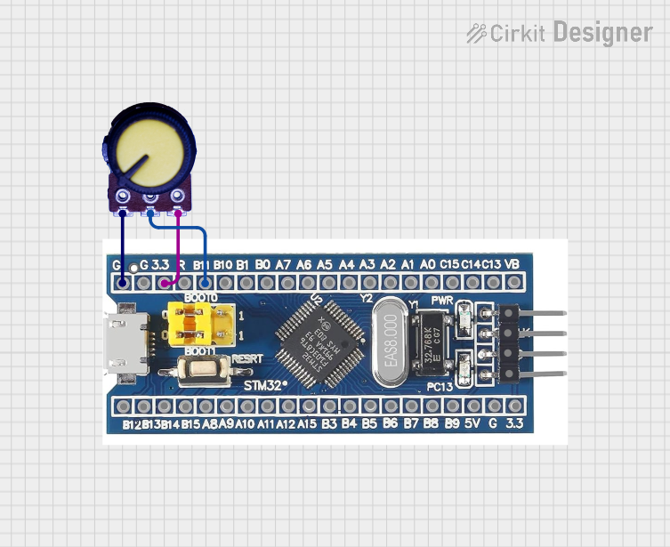
Explore Projects Built with TPL0501 Digital Potentiometer (SPI)
Common Applications
- Audio volume control
- Adjustable gain in amplifiers
- Sensor calibration and trimming
- Programmable voltage dividers
- Signal conditioning in measurement systems
Technical Specifications
The TPL0501 offers the following key technical features:
| Parameter | Value |
|---|---|
| Supply Voltage (VDD) | 2.7V to 5.5V |
| Resistance Range | 100 kΩ |
| Number of Taps | 256 |
| Interface | SPI |
| Operating Temperature | -40°C to +125°C |
| Wiper Current (Max) | ±1 mA |
| End-to-End Resistance Tolerance | ±20% |
| Package Options | SOT-23-6 |
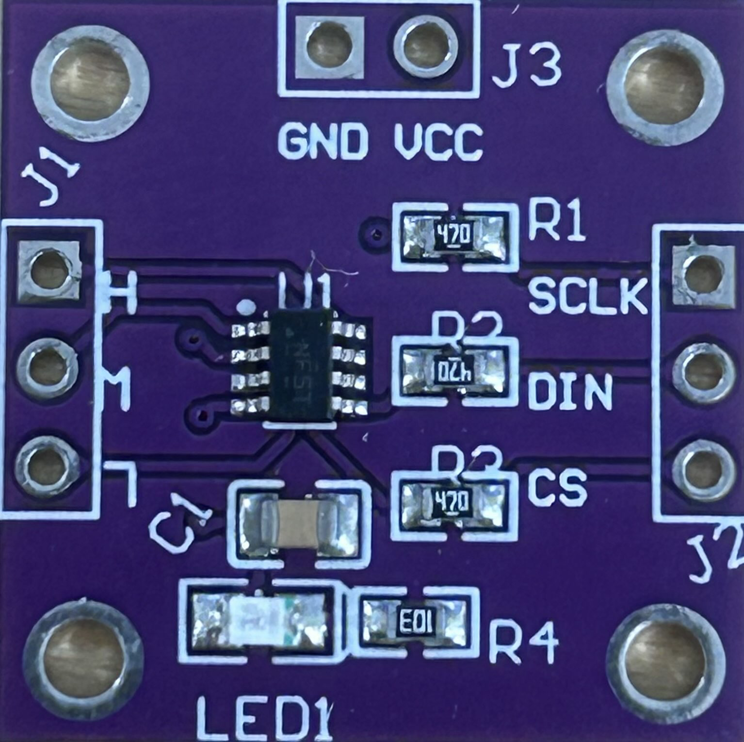
Pin Configuration and Descriptions
The TPL0501 is available in a 6-pin SOT-23 package. The pinout and descriptions are as follows:
| Pin | Name | Description |
|---|---|---|
| 1 | VDD | Positive supply voltage (2.7V to 5.5V). |
| 2 | CS | Chip Select (active low) for SPI communication. |
| 3 | SCK | Serial Clock input for SPI. |
| 4 | SDI | Serial Data Input for SPI. |
| 5 | GND | Ground connection. |
| 6 | RW | Wiper terminal of the potentiometer. |
Usage Instructions
Using the TPL0501 in a Circuit
- Power Supply: Connect the VDD pin to a stable power source (2.7V to 5.5V) and the GND pin to the circuit ground.
- SPI Communication: Connect the CS, SCK, and SDI pins to the corresponding SPI pins of your microcontroller. Ensure proper pull-up or pull-down resistors if required.
- Wiper Connection: Use the RW pin as the adjustable output of the potentiometer. It can be connected to other circuit elements, such as amplifiers or sensors.
- Programming Resistance: Use SPI commands to set the wiper position, which determines the resistance between the RW pin and the ends of the resistor network.
Important Considerations
- Power Supply Stability: Ensure a clean and stable power supply to avoid noise in resistance adjustments.
- SPI Timing: Follow the SPI timing requirements specified in the datasheet to ensure reliable communication.
- Current Limitations: Do not exceed the maximum wiper current of ±1 mA to prevent damage to the device.
- End-to-End Resistance Tolerance: Account for the ±20% tolerance in applications requiring precise resistance values.
Example: Using TPL0501 with Arduino UNO
Below is an example of how to control the TPL0501 using an Arduino UNO:
#include <SPI.h>

// Define SPI pins for TPL0501
const int CS_PIN = 10; // Chip Select pin connected to Arduino pin 10

void setup() {
  // Initialize SPI communication
  SPI.begin();
  pinMode(CS_PIN, OUTPUT);
  digitalWrite(CS_PIN, HIGH); // Set CS pin to HIGH (inactive)

  // Set initial resistance value
  setResistance(128); // Set wiper to mid-point (128 out of 256)
}

void loop() {
  // Example: Adjust resistance dynamically
  for (int i = 0; i <= 255; i++) {
    setResistance(i); // Increment resistance step by step
    delay(100);       // Wait 100ms between steps
  }
}

// Function to set resistance value (0-255)
void setResistance(byte value) {
  digitalWrite(CS_PIN, LOW); // Activate CS pin
  SPI.transfer(value);       // Send resistance value to TPL0501
  digitalWrite(CS_PIN, HIGH); // Deactivate CS pin
}
Notes:
- Ensure the Arduino UNO operates at 5V logic levels, which are compatible with the TPL0501.
- Use a 10 kΩ pull-down resistor on the CS pin if necessary to prevent floating states.
Troubleshooting and FAQs
Common Issues
No Response from the TPL0501
- Cause: Incorrect SPI wiring or configuration.
- Solution: Double-check the connections for CS, SCK, and SDI. Verify the SPI clock speed and mode.
Unexpected Resistance Values
- Cause: End-to-end resistance tolerance or incorrect wiper position.
- Solution: Account for the ±20% tolerance in your design. Verify the SPI commands sent to the device.
Device Overheating
- Cause: Exceeding the maximum wiper current.
- Solution: Ensure the current through the RW pin does not exceed ±1 mA.
Intermittent Operation
- Cause: Noisy power supply or unstable SPI signals.
- Solution: Use decoupling capacitors near the VDD pin and ensure proper grounding.
FAQs
Q1: Can the TPL0501 be used for AC signals?
A1: The TPL0501 is primarily designed for DC applications. For AC signals, ensure the signal amplitude and frequency are within the device's operating limits.
Q2: What is the resolution of the TPL0501?
A2: The TPL0501 has 256 taps, providing a resolution of 1/256 of the total resistance.
Q3: Can I daisy-chain multiple TPL0501 devices?
A3: No, the TPL0501 does not support daisy-chaining. Each device requires a separate CS pin for independent control.
Q4: How do I calculate the resistance at a specific wiper position?
A4: The resistance between the RW pin and one end of the potentiometer is approximately:R = (Position / 255) * Total Resistance.
For example, at position 128 with a 100 kΩ potentiometer, the resistance is ~50 kΩ.