
How to Use 4 x AAA Battery Mount: Examples, Pinouts, and Specs
 Design with 4 x AAA Battery Mount in Cirkit Designer
Introduction
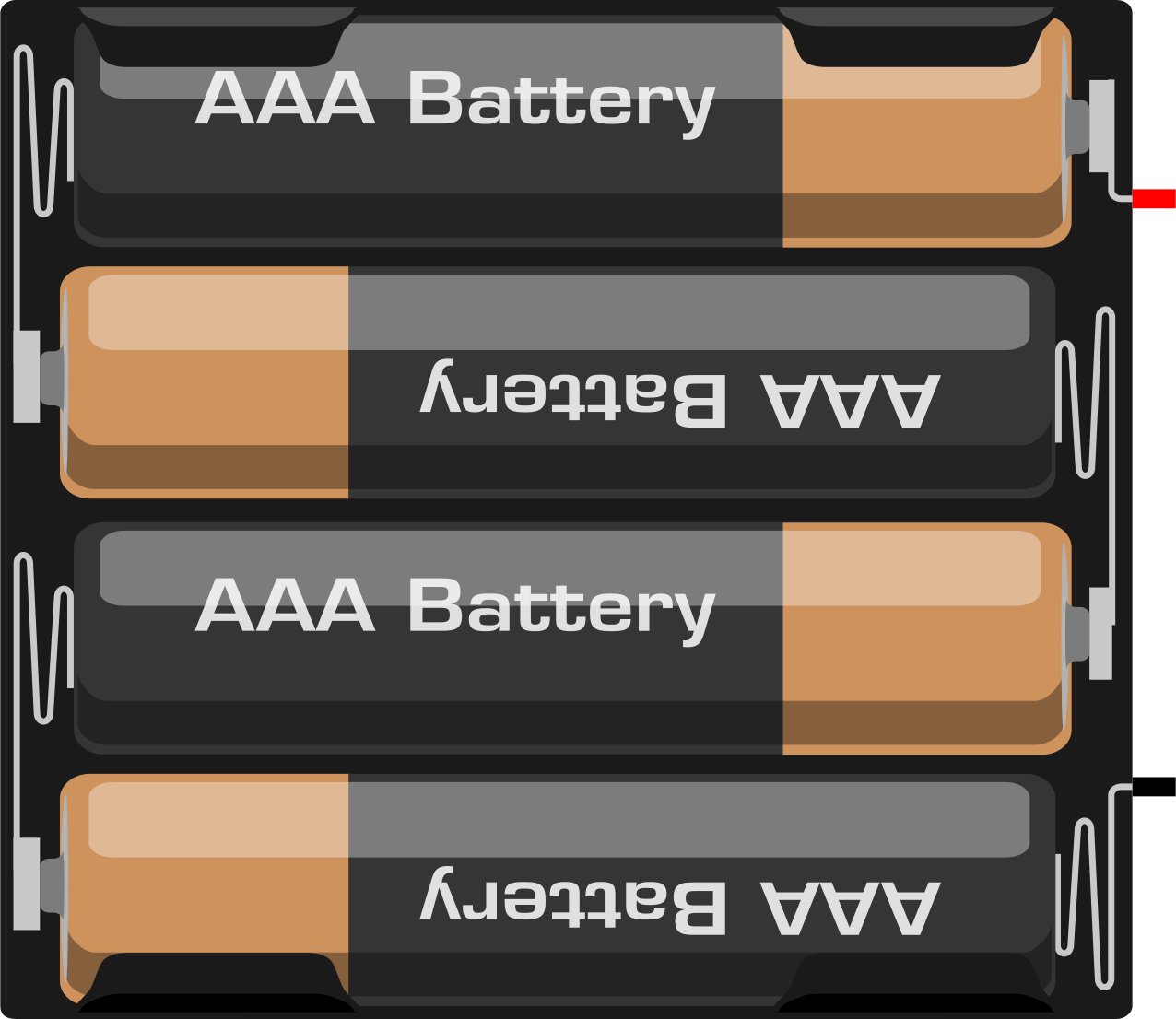
The 4 x AAA Battery Mount is a holder designed to securely house four AAA batteries. It provides a convenient and reliable way to connect batteries in series or parallel, enabling the generation of a stable power source for electronic circuits. This component is widely used in portable devices, DIY electronics projects, and prototyping applications where compact and efficient power solutions are required.
Explore Projects Built with 4 x AAA Battery Mount
 Open Project in Cirkit Designer
 Open Project in Cirkit Designer
 Open Project in Cirkit Designer
 Open Project in Cirkit Designer
Explore Projects Built with 4 x AAA Battery Mount
Open Project in Cirkit DesignerOpen Project in Cirkit DesignerOpen Project in Cirkit DesignerOpen Project in Cirkit DesignerCommon Applications
- Powering small electronic devices such as LED lights, sensors, and microcontrollers.
- DIY projects and prototyping circuits.
- Educational kits for teaching basic electronics.
- Backup power supplies for low-power devices.
Technical Specifications
The 4 x AAA Battery Mount is designed to accommodate standard AAA batteries and provides electrical connections for powering circuits. Below are the key technical details:
General Specifications
| Parameter | Value |
|---|---|
| Battery Type | AAA (1.5V each) |
| Number of Batteries | 4 |
| Output Voltage (Series) | 6V (1.5V x 4) |
| Output Voltage (Parallel) | 1.5V (with increased capacity) |
| Material | Plastic (holder), metal (contacts) |
| Dimensions | Varies by model (approx. 60mm x 30mm x 15mm) |
| Weight | ~15g (without batteries) |
Pin Configuration and Descriptions
The battery mount typically has two wires for electrical connections. The configuration is as follows:
| Wire Color | Description |
|---|---|
| Red | Positive terminal (+) |
| Black | Negative terminal (-) |
Note: Some models may include a switch or additional terminals for flexibility in wiring.
Usage Instructions
Connecting the Battery Mount
- Insert Batteries: Place four AAA batteries into the holder, ensuring correct polarity as indicated on the mount.
- Connect Wires: Use the red wire for the positive terminal and the black wire for the negative terminal. These wires can be soldered, connected to a breadboard, or attached to screw terminals, depending on your project.
- Choose Configuration:
- Series Connection: The default wiring of the mount connects the batteries in series, providing a total voltage of 6V.
- Parallel Connection: To achieve a parallel configuration (1.5V with increased capacity), you will need to rewire the connections manually.
Important Considerations
- Battery Type: Use only AAA batteries (alkaline, NiMH, or lithium). Mixing different types or brands of batteries is not recommended.
- Current Draw: Ensure the connected circuit does not exceed the current rating of the batteries.
- Polarity: Double-check the polarity of the connections to avoid damaging your circuit.
- Heat Management: Avoid short circuits, as they can cause the batteries to overheat.
Example: Powering an Arduino UNO
The 4 x AAA Battery Mount can be used to power an Arduino UNO. Below is an example of how to connect it:
- Insert four AAA batteries into the mount.
- Connect the red wire (positive) to the Arduino's VIN pin.
- Connect the black wire (negative) to the Arduino's GND pin.
Here is a simple Arduino sketch to blink an LED while powered by the battery mount:
// Blink an LED using power from the 4 x AAA Battery Mount
// Ensure the battery mount is connected to the Arduino's VIN and GND pins.

const int ledPin = 13; // Built-in LED pin on Arduino UNO

void setup() {
  pinMode(ledPin, OUTPUT); // Set the LED pin as an output
}

void loop() {
  digitalWrite(ledPin, HIGH); // Turn the LED on
  delay(1000);                // Wait for 1 second
  digitalWrite(ledPin, LOW);  // Turn the LED off
  delay(1000);                // Wait for 1 second
}
Note: Ensure the total voltage (6V) is within the acceptable input range for the Arduino UNO's VIN pin (7-12V recommended). If using rechargeable NiMH batteries (1.2V each), the total voltage will be 4.8V, which is below the recommended range for VIN. In such cases, connect the battery mount to the 5V pin instead.
Troubleshooting and FAQs
Common Issues
No Power Output:
- Cause: Batteries are inserted incorrectly or are depleted.
- Solution: Check the polarity of the batteries and replace them if necessary.
Overheating:
- Cause: Short circuit or excessive current draw.
- Solution: Inspect the wiring for shorts and ensure the connected circuit does not exceed the battery's current rating.
Loose Connections:
- Cause: Wires or battery contacts are not secure.
- Solution: Ensure the wires are properly soldered or connected, and the batteries are firmly seated in the holder.
FAQs
Q: Can I use rechargeable batteries with this mount?
A: Yes, the mount supports rechargeable AAA batteries such as NiMH or lithium-ion. However, note that the voltage of rechargeable batteries (typically 1.2V) is lower than that of alkaline batteries (1.5V).
Q: How do I switch between series and parallel configurations?
A: The default wiring of the mount is for a series connection. To create a parallel configuration, you will need to manually rewire the connections inside the holder. This may require soldering and is not recommended for beginners.
Q: Can I use fewer than four batteries in the mount?
A: No, the mount is designed for four batteries. Using fewer batteries will result in an incomplete circuit and no power output.
Q: Is the mount waterproof?
A: No, the mount is not waterproof. Avoid exposing it to moisture or liquids to prevent damage.
By following this documentation, you can effectively use the 4 x AAA Battery Mount in your electronic projects.