How to Use E2-Q2 Encoder: Examples, Pinouts, and Specs

Introduction
The E2-Q2 Encoder by Robocore is a rotary encoder designed to convert the angular position or motion of a rotating shaft into an analog or digital signal. This encoder is widely used in applications requiring precise position feedback, such as robotics, automation systems, motor control, and CNC machines. Its compact design and reliable performance make it an excellent choice for both hobbyists and professionals.
Explore Projects Built with E2-Q2 Encoder


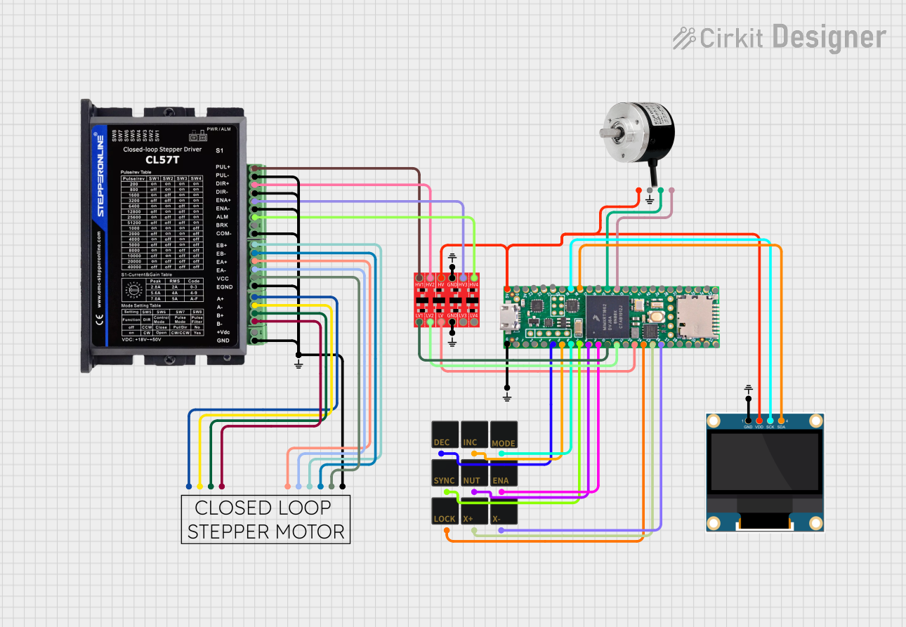
Explore Projects Built with E2-Q2 Encoder
Common Applications:
- Robotics: For precise motor position and speed feedback.
- CNC Machines: To monitor and control axis movement.
- Automation Systems: For position tracking in conveyor belts or robotic arms.
- Motor Control: To provide feedback for closed-loop control systems.
Technical Specifications
Below are the key technical details of the E2-Q2 Encoder:
| Parameter | Specification |
|---|---|
| Manufacturer | Robocore |
| Part ID | E2-Q2 |
| Output Signal Type | Quadrature (A and B channels) |
| Resolution | 360 pulses per revolution (PPR) |
| Operating Voltage | 5V DC |
| Operating Current | 20 mA (typical) |
| Maximum Rotational Speed | 6000 RPM |
| Output Format | Digital (TTL compatible) |
| Operating Temperature | -10°C to 70°C |
| Shaft Diameter | 6 mm |
| Mounting Hole Diameter | 3 mm |
Pin Configuration
The E2-Q2 Encoder has a 5-pin interface. The pinout is as follows:
| Pin | Name | Description |
|---|---|---|
| 1 | VCC | Power supply input (5V DC) |
| 2 | GND | Ground |
| 3 | A | Channel A output (quadrature signal) |
| 4 | B | Channel B output (quadrature signal) |
| 5 | Z | Index pulse output (optional, 1 pulse per revolution) |
Usage Instructions
How to Use the E2-Q2 Encoder in a Circuit
- Power Connection: Connect the VCC pin to a 5V DC power source and the GND pin to the ground of your circuit.
- Signal Outputs: Connect the A and B pins to the input pins of a microcontroller or motor driver to read the quadrature signals. If needed, connect the Z pin for the index pulse.
- Pull-Up Resistors: If the encoder outputs are open-collector, use pull-up resistors (e.g., 10kΩ) on the A, B, and Z lines to ensure proper signal levels.
- Signal Decoding: Use a microcontroller or dedicated encoder interface to decode the quadrature signals and determine the direction and position of the shaft.
Important Considerations
- Debouncing: Use software or hardware debouncing to filter out noise in the encoder signals.
- Mounting: Ensure the encoder is securely mounted to avoid misalignment or vibration, which can affect accuracy.
- Speed Limit: Do not exceed the maximum rotational speed of 6000 RPM to prevent signal errors or damage.
- Cable Length: Keep the cable length as short as possible to minimize signal degradation.
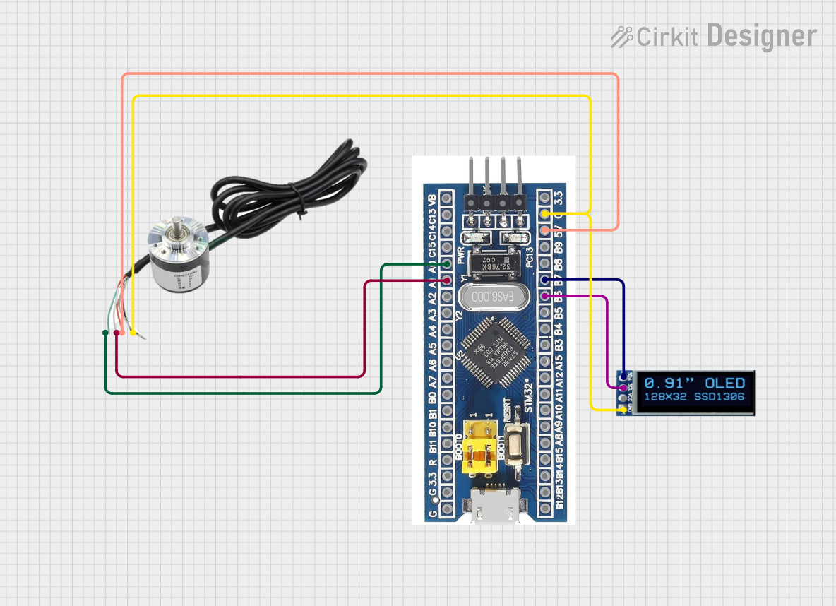
Example: Connecting the E2-Q2 Encoder to an Arduino UNO
Below is an example of how to connect and use the E2-Q2 Encoder with an Arduino UNO to read position and direction:
Circuit Diagram
- Connect the VCC pin of the encoder to the 5V pin on the Arduino.
- Connect the GND pin of the encoder to the GND pin on the Arduino.
- Connect the A pin to digital pin 2 on the Arduino.
- Connect the B pin to digital pin 3 on the Arduino.
Arduino Code
// E2-Q2 Encoder Example with Arduino UNO
// Reads the encoder position and direction using interrupts

#define ENCODER_PIN_A 2  // Pin connected to Channel A
#define ENCODER_PIN_B 3  // Pin connected to Channel B

volatile int encoderPosition = 0;  // Tracks the encoder position
volatile int lastEncoded = 0;     // Stores the last encoder state

void setup() {
  pinMode(ENCODER_PIN_A, INPUT);
  pinMode(ENCODER_PIN_B, INPUT);

  // Enable pull-up resistors for stable signal reading
  digitalWrite(ENCODER_PIN_A, HIGH);
  digitalWrite(ENCODER_PIN_B, HIGH);

  // Attach interrupts to the encoder pins
  attachInterrupt(digitalPinToInterrupt(ENCODER_PIN_A), updateEncoder, CHANGE);
  attachInterrupt(digitalPinToInterrupt(ENCODER_PIN_B), updateEncoder, CHANGE);

  Serial.begin(9600);  // Initialize serial communication
}

void loop() {
  // Print the encoder position to the Serial Monitor
  Serial.print("Encoder Position: ");
  Serial.println(encoderPosition);
  delay(100);  // Update every 100ms
}

void updateEncoder() {
  // Read the current state of Channel A and Channel B
  int MSB = digitalRead(ENCODER_PIN_A);  // Most Significant Bit
  int LSB = digitalRead(ENCODER_PIN_B);  // Least Significant Bit

  int encoded = (MSB << 1) | LSB;  // Combine the two bits
  int sum = (lastEncoded << 2) | encoded;  // Track state changes

  // Determine direction and update position
  if (sum == 0b1101 || sum == 0b0100 || sum == 0b0010 || sum == 0b1011) {
    encoderPosition++;
  } else if (sum == 0b1110 || sum == 0b0111 || sum == 0b0001 || sum == 0b1000) {
    encoderPosition--;
  }

  lastEncoded = encoded;  // Update the last state
}
Notes:
- Ensure the encoder is properly aligned with the shaft to avoid signal errors.
- Use a stable 5V power supply to prevent fluctuations in the encoder output.
Troubleshooting and FAQs
Common Issues and Solutions
No Signal Output:
- Check the power connections (VCC and GND).
- Verify that pull-up resistors are used if required.
- Ensure the encoder is not damaged or misaligned.
Incorrect Position Readings:
- Verify the connections to the A and B channels.
- Check for noise or interference in the signal lines.
- Ensure the rotational speed does not exceed 6000 RPM.
Signal Noise or Jitter:
- Use shielded cables to reduce electromagnetic interference.
- Implement software or hardware debouncing.
Encoder Not Responding:
- Confirm that the microcontroller pins are configured as inputs.
- Test the encoder with a multimeter to ensure proper signal output.
FAQs
Q: Can the E2-Q2 Encoder be used with a 3.3V microcontroller?
A: The encoder requires a 5V power supply, but its output signals are TTL compatible. Use a level shifter if your microcontroller operates at 3.3V.
Q: What is the purpose of the Z (index) pin?
A: The Z pin provides a single pulse per revolution, which can be used for homing or zeroing the position.
Q: How do I calculate the angular position from the encoder output?
A: Divide the encoder position count by the resolution (360 PPR) and multiply by 360° to get the angular position in degrees.
Q: Can I use the E2-Q2 Encoder for speed measurement?
A: Yes, by measuring the time between pulses on the A or B channel, you can calculate the rotational speed.
This concludes the documentation for the E2-Q2 Encoder. For further assistance, refer to the manufacturer's datasheet or contact Robocore support.