Cirkit Designer Logo
Cirkit Designer
Your all-in-one circuit design IDE
Home / 
Component Documentation

How to Use STEP DOWN XY 3606: Examples, Pinouts, and Specs

Image of STEP DOWN XY 3606
Cirkit Designer LogoDesign with STEP DOWN XY 3606 in Cirkit Designer

Introduction

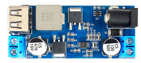
The STEP DOWN XY 3606 is a high-efficiency DC-DC buck converter module designed to step down voltage from a higher level to a lower level. This versatile component is widely used in various applications where voltage regulation is crucial. It is particularly useful in battery-powered devices, power supply units, and embedded systems.

Explore Projects Built with STEP DOWN XY 3606

Use Cirkit Designer to design, explore, and prototype these projects online. Some projects support real-time simulation. Click "Open Project" to start designing instantly!
CNC Machine Control System with Dual tb6600 Stepper Drivers and MAch3 USB Interface
Image of Jayshree CNC: A project utilizing STEP DOWN XY 3606 in a practical application
This circuit appears to be a control system for a CNC machine or similar automated equipment. It includes two tb6600 Micro Stepping Motor Drivers for controlling stepper motors, a DC power source with a step-down buck converter to provide the necessary voltage levels, and a 4-channel relay module for switching higher power loads. The MAch3 CNC USB interface suggests the system is designed to interface with computer numerical control software, and the RMCS_3001 BLDC Driver indicates the presence of a brushless DC motor control. The Tiva C launchpad microcontroller and various connectors imply that the system is modular and may be programmable for specific automation tasks.
Cirkit Designer LogoOpen Project in Cirkit Designer
Battery-Powered UPS with Step-Down Buck Converter and BMS
Image of Mini ups: A project utilizing STEP DOWN XY 3606 in a practical application
This circuit is a power management system that steps down a 240V AC input to a lower DC voltage using a buck converter, which then powers a 40W UPS. The UPS is controlled by a rocker switch and is backed up by a battery management system (BMS) connected to three 3.7V batteries in series, ensuring continuous power supply.
Cirkit Designer LogoOpen Project in Cirkit Designer
Arduino Nano Based GPS Tracker with GSM Communication and Accelerometer
Image of Circuit Aayush: A project utilizing STEP DOWN XY 3606 in a practical application
This circuit is designed for communication and location tracking purposes. It features an Arduino Nano interfaced with a SIM800L GSM module for cellular connectivity, a GPS NEO 6M module for obtaining geographical coordinates, and an AITrip ADXL335 GY-61 accelerometer for motion sensing. The LM2596 Step Down Module is used to regulate the power supply to the components.
Cirkit Designer LogoOpen Project in Cirkit Designer
Dual Motor Control Circuit with Directional Switching and Voltage Regulation
Image of Pencuci Kipas: A project utilizing STEP DOWN XY 3606 in a practical application
This circuit features a 12V battery connected through a rocker switch to two buck converters, one of which steps down the voltage to power two DC mini metal gear motors, and the other is connected to a directional switch that controls a third DC mini metal gear motor. The XL4015 5A DC Buck Step-down converter's output is connected to two motors, allowing them to run at a reduced voltage, while the other buck converter's output is routed through a directional switch to control the direction of the third motor.
Cirkit Designer LogoOpen Project in Cirkit Designer

Explore Projects Built with STEP DOWN XY 3606

Use Cirkit Designer to design, explore, and prototype these projects online. Some projects support real-time simulation. Click "Open Project" to start designing instantly!
Image of Jayshree CNC: A project utilizing STEP DOWN XY 3606 in a practical application
CNC Machine Control System with Dual tb6600 Stepper Drivers and MAch3 USB Interface
This circuit appears to be a control system for a CNC machine or similar automated equipment. It includes two tb6600 Micro Stepping Motor Drivers for controlling stepper motors, a DC power source with a step-down buck converter to provide the necessary voltage levels, and a 4-channel relay module for switching higher power loads. The MAch3 CNC USB interface suggests the system is designed to interface with computer numerical control software, and the RMCS_3001 BLDC Driver indicates the presence of a brushless DC motor control. The Tiva C launchpad microcontroller and various connectors imply that the system is modular and may be programmable for specific automation tasks.
Cirkit Designer LogoOpen Project in Cirkit Designer
Image of Mini ups: A project utilizing STEP DOWN XY 3606 in a practical application
Battery-Powered UPS with Step-Down Buck Converter and BMS
This circuit is a power management system that steps down a 240V AC input to a lower DC voltage using a buck converter, which then powers a 40W UPS. The UPS is controlled by a rocker switch and is backed up by a battery management system (BMS) connected to three 3.7V batteries in series, ensuring continuous power supply.
Cirkit Designer LogoOpen Project in Cirkit Designer
Image of Circuit Aayush: A project utilizing STEP DOWN XY 3606 in a practical application
Arduino Nano Based GPS Tracker with GSM Communication and Accelerometer
This circuit is designed for communication and location tracking purposes. It features an Arduino Nano interfaced with a SIM800L GSM module for cellular connectivity, a GPS NEO 6M module for obtaining geographical coordinates, and an AITrip ADXL335 GY-61 accelerometer for motion sensing. The LM2596 Step Down Module is used to regulate the power supply to the components.
Cirkit Designer LogoOpen Project in Cirkit Designer
Image of Pencuci Kipas: A project utilizing STEP DOWN XY 3606 in a practical application
Dual Motor Control Circuit with Directional Switching and Voltage Regulation
This circuit features a 12V battery connected through a rocker switch to two buck converters, one of which steps down the voltage to power two DC mini metal gear motors, and the other is connected to a directional switch that controls a third DC mini metal gear motor. The XL4015 5A DC Buck Step-down converter's output is connected to two motors, allowing them to run at a reduced voltage, while the other buck converter's output is routed through a directional switch to control the direction of the third motor.
Cirkit Designer LogoOpen Project in Cirkit Designer

Common Applications and Use Cases

  • Battery-Powered Devices: Efficiently step down voltage to prolong battery life.
  • Power Supply Units: Provide stable voltage to sensitive electronic components.
  • Embedded Systems: Regulate voltage for microcontrollers and other digital circuits.
  • LED Drivers: Supply constant voltage to LED arrays.
  • Arduino Projects: Commonly used to power Arduino boards and peripherals.

Technical Specifications

Key Technical Details

Parameter Value
Input Voltage 4.0V to 38V
Output Voltage 1.25V to 36V
Output Current Up to 5A (with heat sink)
Efficiency Up to 96%
Switching Frequency 150 kHz
Operating Temperature -40°C to +85°C
Dimensions 45mm x 20mm x 14mm

Pin Configuration and Descriptions

Pin Number Pin Name Description
1 VIN Input voltage (4.0V to 38V)
2 GND Ground
3 VOUT Output voltage (1.25V to 36V)
4 EN Enable pin (active high, connect to VIN to enable)

Usage Instructions

How to Use the Component in a Circuit

  1. Connect the Input Voltage:

    • Connect the positive terminal of your power source to the VIN pin.
    • Connect the negative terminal of your power source to the GND pin.
  2. Connect the Output Voltage:

    • Connect the VOUT pin to the load that requires the stepped-down voltage.
    • Ensure the GND pin is also connected to the ground of the load.
  3. Enable the Module:

    • To enable the module, connect the EN pin to the VIN pin.
    • If you wish to control the enable function, you can connect the EN pin to a microcontroller or a switch.
  4. Adjust the Output Voltage:

    • Use the onboard potentiometer to adjust the output voltage to the desired level.
    • Measure the output voltage with a multimeter while adjusting.

Important Considerations and Best Practices

  • Heat Dissipation: For high current applications, ensure proper heat dissipation by attaching a heat sink to the module.
  • Input Voltage: Always ensure the input voltage is within the specified range (4.0V to 38V).
  • Polarity: Double-check the polarity of the connections to avoid damaging the module.
  • Load Requirements: Ensure the load does not exceed the maximum output current of 5A.

Example: Using XY 3606 with Arduino UNO

To power an Arduino UNO using the XY 3606, follow these steps:

  1. Connect the Input Voltage:

    • Connect a 12V power source to the VIN and GND pins of the XY 3606.
  2. Connect the Output Voltage:

    • Adjust the output voltage to 5V using the potentiometer.
    • Connect the VOUT pin to the 5V pin of the Arduino UNO.
    • Connect the GND pin to the GND pin of the Arduino UNO.
  3. Enable the Module:

    • Connect the EN pin to the VIN pin to enable the module.

Troubleshooting and FAQs

Common Issues Users Might Face

  1. No Output Voltage:

    • Solution: Check the input voltage and ensure it is within the specified range. Verify that the EN pin is connected to VIN.
  2. Overheating:

    • Solution: Ensure proper heat dissipation by attaching a heat sink. Reduce the load current if necessary.
  3. Output Voltage Not Stable:

    • Solution: Check the connections and ensure they are secure. Verify that the input voltage is stable and within the specified range.

FAQs

Q1: Can I use the XY 3606 to power my Raspberry Pi?

  • A1: Yes, you can use the XY 3606 to step down the voltage to 5V and power your Raspberry Pi. Ensure the output current is sufficient for your Raspberry Pi model.

Q2: How do I adjust the output voltage?

  • A2: Use the onboard potentiometer to adjust the output voltage. Measure the voltage with a multimeter while adjusting.

Q3: What is the maximum input voltage for the XY 3606?

  • A3: The maximum input voltage is 38V. Ensure the input voltage does not exceed this limit to avoid damaging the module.

Q4: Can I use the XY 3606 in automotive applications?

  • A4: Yes, the XY 3606 can be used in automotive applications, provided the input voltage is within the specified range and proper heat dissipation is ensured.

By following this documentation, users can effectively utilize the STEP DOWN XY 3606 DC-DC buck converter module in their projects, ensuring efficient and reliable voltage regulation.