
How to Use RCBO AVDT32ML C25 30mA: Examples, Pinouts, and Specs
 Design with RCBO AVDT32ML C25 30mA in Cirkit Designer
Introduction
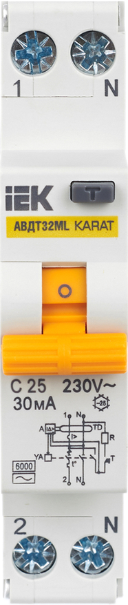
The RCBO AVDT32ML C25 30mA (Manufacturer Part ID: MVD12-1-025-C-030) is a Residual Current Circuit Breaker with Overcurrent protection (RCBO) manufactured by IEK. This device combines the functionality of a Residual Current Device (RCD) and a Miniature Circuit Breaker (MCB) into a single unit. It is designed to protect electrical circuits from overcurrent (overload and short circuit) and to safeguard users from electric shock caused by earth faults.
Explore Projects Built with RCBO AVDT32ML C25 30mA
 Open Project in Cirkit Designer
 Open Project in Cirkit Designer
 Open Project in Cirkit Designer
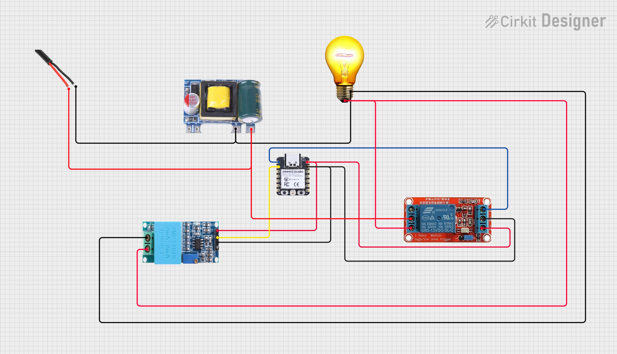 Open Project in Cirkit Designer
Explore Projects Built with RCBO AVDT32ML C25 30mA
Open Project in Cirkit DesignerOpen Project in Cirkit DesignerOpen Project in Cirkit DesignerOpen Project in Cirkit DesignerCommon Applications and Use Cases
- Residential and commercial electrical installations
- Protection of circuits in industrial environments
- Safeguarding sensitive equipment from electrical faults
- Ensuring compliance with safety standards in electrical systems
Technical Specifications
The following table outlines the key technical details of the RCBO AVDT32ML C25 30mA:
| Parameter | Specification |
|---|---|
| Manufacturer | IEK |
| Part ID | MVD12-1-025-C-030 |
| Rated Current (In) | 25A |
| Rated Residual Current (IΔn) | 30mA |
| Rated Voltage (Un) | 230V AC |
| Frequency | 50/60 Hz |
| Breaking Capacity | 6kA |
| Tripping Curve | Type C |
| Number of Poles | 1P+N (Single Pole + Neutral) |
| Mounting Type | DIN Rail (35mm) |
| Operating Temperature Range | -25°C to +40°C |
| Degree of Protection | IP20 |
Pin Configuration and Descriptions
The RCBO has the following terminal connections:
| Terminal | Description |
|---|---|
| L (Line In) | Connects to the incoming live (phase) wire |
| N (Neutral In) | Connects to the incoming neutral wire |
| L (Line Out) | Connects to the outgoing live (phase) wire |
| N (Neutral Out) | Connects to the outgoing neutral wire |
Usage Instructions
How to Use the RCBO in a Circuit
- Mounting: Install the RCBO on a standard 35mm DIN rail in the distribution board.
- Wiring:
- Connect the incoming live wire to the L (Line In) terminal.
- Connect the incoming neutral wire to the N (Neutral In) terminal.
- Connect the outgoing live wire to the L (Line Out) terminal.
- Connect the outgoing neutral wire to the N (Neutral Out) terminal.
- Testing:
- After installation, press the Test Button on the RCBO to verify its functionality. The device should trip immediately, indicating proper operation.
- Resetting:
- To reset the RCBO after a trip, switch the lever to the "OFF" position and then back to the "ON" position.
Important Considerations and Best Practices
- Ensure that the RCBO's rated current (25A) matches the circuit's load requirements.
- Do not exceed the rated residual current sensitivity (30mA) for earth fault protection.
- Always turn off the main power supply before installing or servicing the RCBO.
- Use appropriate wire sizes as per the circuit's current rating to avoid overheating.
- Regularly test the RCBO using the test button to ensure it remains functional.
Arduino Integration
The RCBO is not directly compatible with Arduino or other microcontrollers, as it is a high-voltage protection device. However, it can be used in circuits that power Arduino-based systems to ensure safety and prevent damage from electrical faults.
Troubleshooting and FAQs
Common Issues and Solutions
| Issue | Possible Cause | Solution |
|---|---|---|
| RCBO does not trip when the test button is pressed | Faulty RCBO or improper wiring | Verify wiring connections and replace the RCBO if necessary. |
| RCBO trips frequently without load | Earth leakage or faulty wiring in the circuit | Inspect the circuit for insulation damage or loose connections. |
| RCBO trips under normal load conditions | Overcurrent or incorrect load rating | Ensure the load does not exceed 25A and check for short circuits. |
| RCBO does not reset after tripping | Persistent fault in the circuit | Identify and resolve the fault before attempting to reset. |
FAQs
Can the RCBO be used in outdoor installations?
- No, the RCBO has an IP20 rating and is not suitable for outdoor use. It must be installed in a protected enclosure.
What is the purpose of the test button?
- The test button simulates a fault condition to verify the RCBO's functionality. It should be tested periodically.
Can this RCBO protect against lightning strikes?
- No, the RCBO is not designed for surge protection. Use a surge protection device (SPD) for lightning protection.
What is the difference between Type C and Type B tripping curves?
- Type C RCBOs are designed for circuits with moderate inrush currents (e.g., lighting or small motors), while Type B is for purely resistive loads.
By following this documentation, users can safely and effectively install and operate the RCBO AVDT32ML C25 30mA in their electrical systems.