How to Use BMM150: Examples, Pinouts, and Specs
Introduction
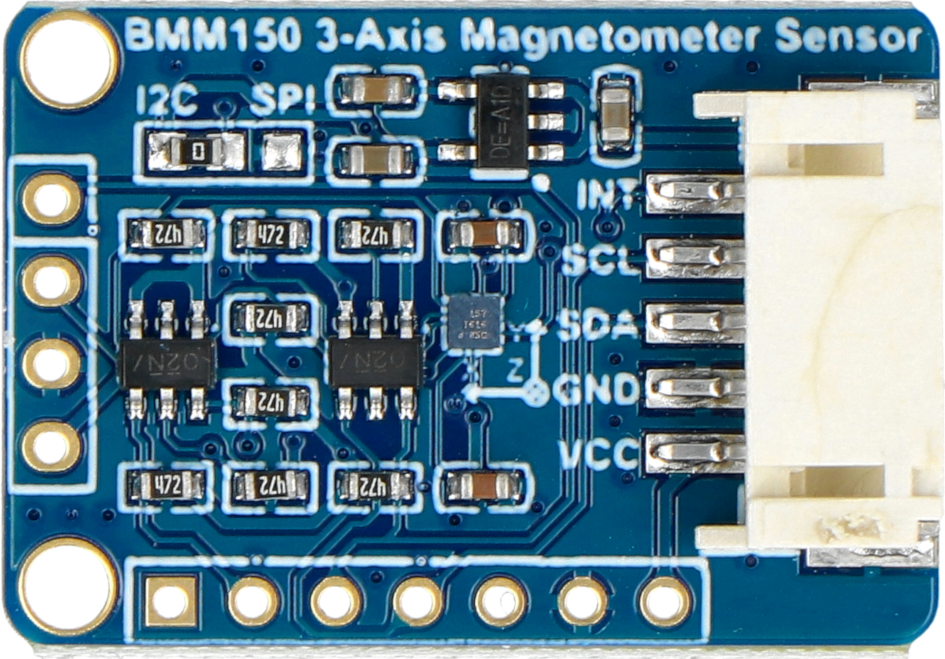
The BMM150 is a 3-axis digital magnetometer manufactured by WAVESHARE. It is designed for precise measurement of magnetic fields and is widely used in applications requiring orientation detection, navigation, and augmented reality. With its low power consumption and high sensitivity, the BMM150 is ideal for portable devices, wearables, and IoT applications.
Explore Projects Built with BMM150


Explore Projects Built with BMM150
Common Applications
- Electronic compasses
- Navigation systems
- Augmented reality (AR) devices
- Robotics and drones
- Industrial automation
- Gaming controllers
Technical Specifications
The BMM150 is a highly integrated magnetometer with the following key specifications:
| Parameter | Value |
|---|---|
| Manufacturer Part ID | BMM150 |
| Operating Voltage | 1.8V to 3.6V |
| Interface | I2C and SPI |
| Measurement Range | ±1300 µT (X, Y-axis), ±2500 µT (Z-axis) |
| Sensitivity | 0.3 µT/LSB |
| Power Consumption | 170 µA (typical, normal mode) |
| Operating Temperature Range | -40°C to +85°C |
| Output Data Rate (ODR) | 10 Hz to 100 Hz |
| Package Type | LGA-12 (2.0 mm x 2.0 mm x 0.95 mm) |
Pin Configuration and Descriptions
The BMM150 has 12 pins, as described in the table below:
| Pin Number | Pin Name | Description |
|---|---|---|
| 1 | GND | Ground |
| 2 | VDD | Power supply (1.8V to 3.6V) |
| 3 | VDDIO | I/O voltage supply |
| 4 | CSB | Chip select for SPI (active low) |
| 5 | SDO | SPI data output |
| 6 | SDA/SDI | I2C data line / SPI data input |
| 7 | SCL/SCK | I2C clock line / SPI clock |
| 8 | INT | Interrupt output |
| 9-12 | NC | Not connected |
Usage Instructions
How to Use the BMM150 in a Circuit
- Power Supply: Connect the VDD pin to a 1.8V to 3.6V power source and the GND pin to ground. Ensure the VDDIO pin is connected to the appropriate I/O voltage level.
- Communication Interface: Choose between I2C or SPI for communication:
- For I2C, connect the SDA and SCL pins to the corresponding lines on your microcontroller.
- For SPI, connect the CSB, SDO, SDA/SDI, and SCL/SCK pins to the respective SPI lines.
- Pull-Up Resistors: If using I2C, add pull-up resistors (typically 4.7 kΩ) to the SDA and SCL lines.
- Interrupt Pin: Optionally, connect the INT pin to a GPIO pin on your microcontroller for interrupt-based operation.
- Bypass Capacitor: Place a 0.1 µF capacitor close to the VDD pin for power supply decoupling.
Important Considerations and Best Practices
- Magnetic Interference: Avoid placing the BMM150 near ferromagnetic materials or strong magnetic fields to prevent measurement errors.
- Calibration: Perform a one-time calibration to account for hard and soft iron distortions in the environment.
- Data Rate: Choose an appropriate output data rate (ODR) based on your application requirements to balance power consumption and performance.
- Orientation: Mount the sensor on the PCB in a way that aligns with your application's coordinate system.
Example: Using the BMM150 with Arduino UNO
Below is an example of interfacing the BMM150 with an Arduino UNO using the I2C interface:
#include <Wire.h>

// BMM150 I2C address
#define BMM150_I2C_ADDR 0x10

void setup() {
  Wire.begin(); // Initialize I2C communication
  Serial.begin(9600); // Initialize serial communication for debugging

  // Initialize the BMM150
  Wire.beginTransmission(BMM150_I2C_ADDR);
  Wire.write(0x4B); // Power control register
  Wire.write(0x01); // Set to normal mode
  Wire.endTransmission();

  Serial.println("BMM150 initialized.");
}

void loop() {
  int16_t magX, magY, magZ;

  // Request data from BMM150
  Wire.beginTransmission(BMM150_I2C_ADDR);
  Wire.write(0x42); // Start address of magnetic data
  Wire.endTransmission();
  Wire.requestFrom(BMM150_I2C_ADDR, 6); // Request 6 bytes of data

  if (Wire.available() == 6) {
    magX = Wire.read() | (Wire.read() << 8); // Combine LSB and MSB for X-axis
    magY = Wire.read() | (Wire.read() << 8); // Combine LSB and MSB for Y-axis
    magZ = Wire.read() | (Wire.read() << 8); // Combine LSB and MSB for Z-axis

    // Print magnetic field data
    Serial.print("Magnetic Field (µT) - X: ");
    Serial.print(magX);
    Serial.print(", Y: ");
    Serial.print(magY);
    Serial.print(", Z: ");
    Serial.println(magZ);
  }

  delay(500); // Wait for 500ms before the next reading
}
Troubleshooting and FAQs
Common Issues and Solutions
No Data Output:
- Ensure the BMM150 is powered correctly and the I2C/SPI connections are secure.
- Verify the I2C address (default is 0x10) or SPI configuration.
- Check if the sensor is in sleep mode and configure it to normal mode.
Inaccurate Measurements:
- Perform a calibration to account for environmental magnetic distortions.
- Avoid placing the sensor near strong magnetic fields or ferromagnetic materials.
Communication Errors:
- Check pull-up resistors on the I2C lines.
- Ensure the microcontroller's I2C/SPI clock speed is compatible with the BMM150.
FAQs
Q: Can the BMM150 be used for 3D orientation detection?
A: Yes, the BMM150 can measure magnetic fields along three axes, making it suitable for 3D orientation and heading detection.
Q: What is the maximum distance for I2C communication?
A: The maximum distance depends on the pull-up resistor values and the capacitance of the I2C bus. Typically, it is limited to a few meters.
Q: How do I perform a calibration?
A: Rotate the sensor in all directions to collect data for hard and soft iron calibration. Use this data to compute correction factors.
Q: Can the BMM150 operate in low-power mode?
A: Yes, the BMM150 supports low-power mode for energy-efficient applications. Configure the power control register accordingly.