How to Use TI-RSLK MAX Gearmotor and Encoder Assembly for Romi: Examples, Pinouts, and Specs
Introduction
The TI-RSLK MAX Gearmotor and Encoder Assembly for Romi (Manufacturer Part ID: 3675) is a compact and efficient gearmotor designed specifically for the Romi robot platform. Manufactured by Pololu, this assembly integrates a DC motor, a gearbox, and an encoder, providing precise position and speed feedback. This makes it ideal for applications requiring accurate control and movement, such as robotics, automation, and educational projects.
Explore Projects Built with TI-RSLK MAX Gearmotor and Encoder Assembly for Romi


Explore Projects Built with TI-RSLK MAX Gearmotor and Encoder Assembly for Romi
Common Applications
- Robotics platforms (e.g., Romi chassis)
- Autonomous vehicles
- Educational robotics kits
- Motion control systems
- Prototyping and research in mechatronics
Technical Specifications
Key Specifications
| Parameter | Value |
|---|---|
| Manufacturer | Pololu |
| Part ID | 3675 |
| Motor Type | Brushed DC motor with integrated encoder |
| Gear Ratio | 120:1 |
| Operating Voltage Range | 6 V to 9 V |
| No-Load Speed (at 6 V) | ~150 RPM |
| Stall Torque (at 6 V) | ~1.5 kg·cm |
| Encoder Resolution | 12 counts per revolution of the motor shaft (1440 counts per revolution of the gearbox output shaft) |
| Dimensions | 25 mm × 25 mm × 25 mm (approx.) |
| Weight | ~50 g |
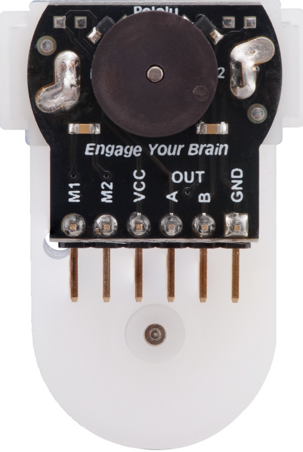
Pin Configuration and Descriptions
The encoder assembly includes a 6-pin header for interfacing with the motor and encoder. The pinout is as follows:
| Pin Number | Label | Description |
|---|---|---|
| 1 | VCC | Power supply for the encoder (3.3 V or 5 V, depending on your system) |
| 2 | GND | Ground connection |
| 3 | A | Encoder channel A output (quadrature signal) |
| 4 | B | Encoder channel B output (quadrature signal) |
| 5 | M+ | Motor positive terminal |
| 6 | M- | Motor negative terminal |
Usage Instructions
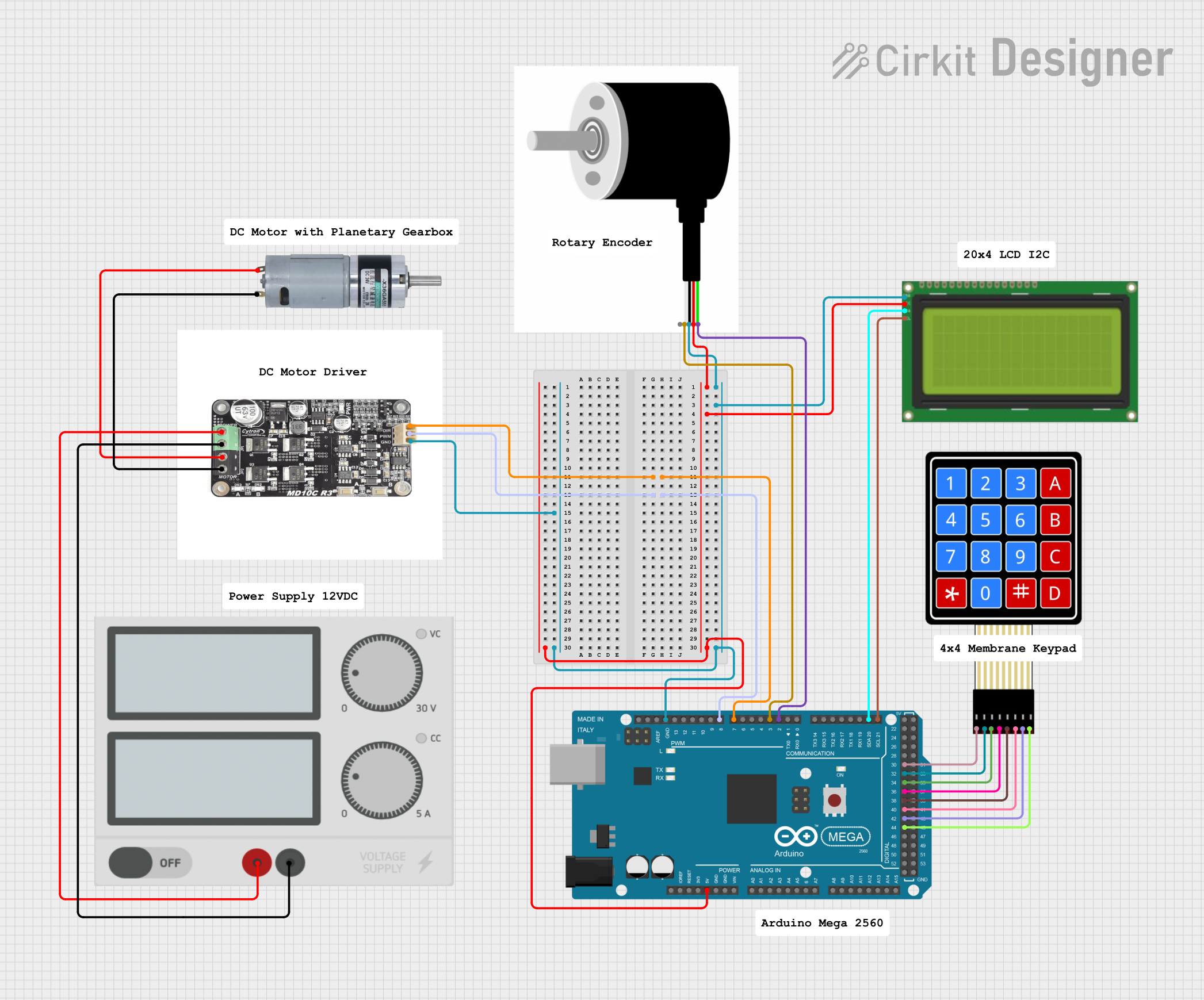
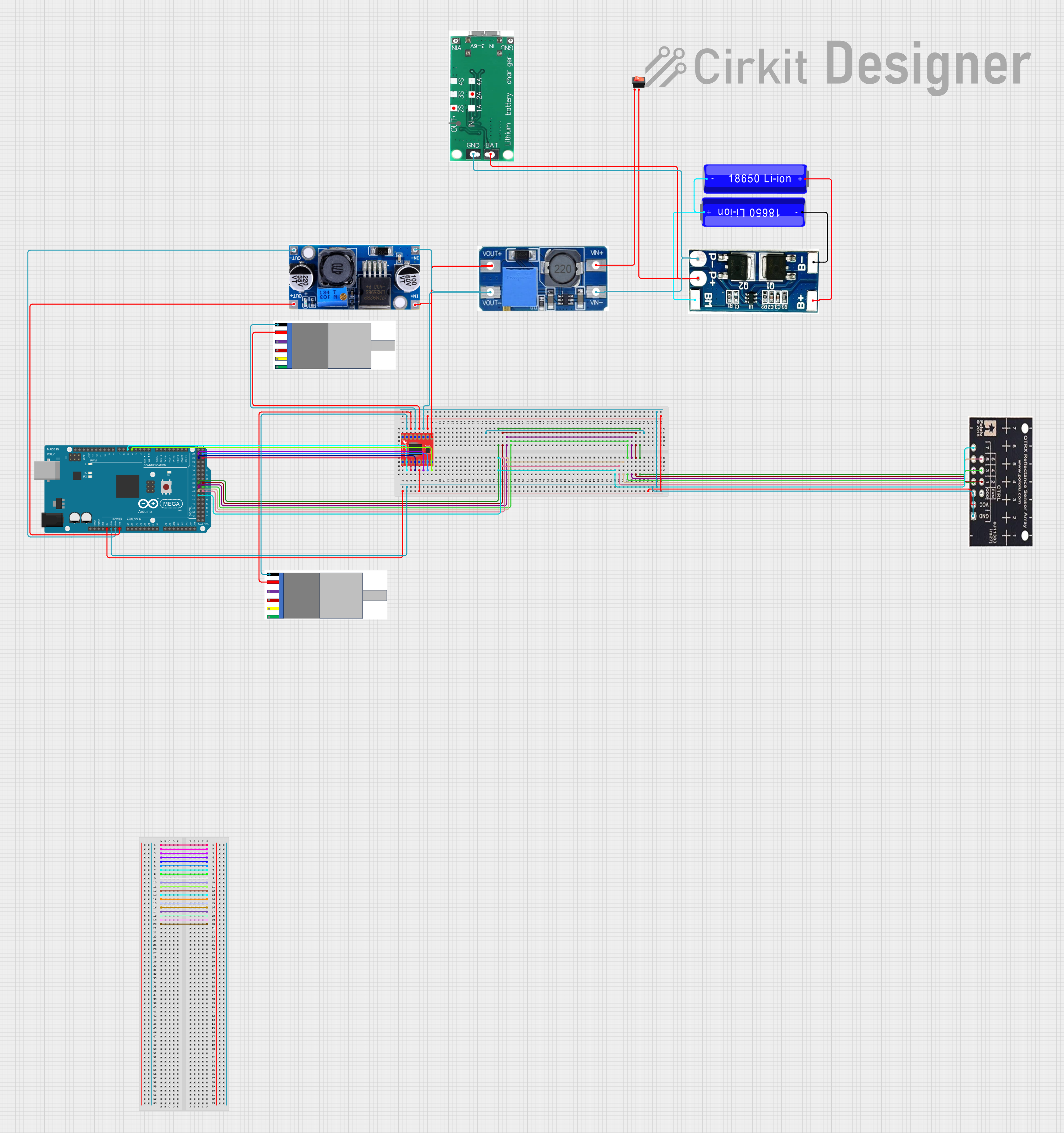
How to Use the Component in a Circuit
Powering the Motor and Encoder:
- Connect the motor terminals (M+ and M-) to a motor driver capable of handling the motor's voltage and current requirements.
- Supply the encoder with a regulated voltage (3.3 V or 5 V) via the VCC pin and connect the GND pin to your system ground.
Reading Encoder Signals:
- Connect the encoder outputs (A and B) to digital input pins on your microcontroller or motor controller.
- Use these signals to determine the motor's position and direction of rotation using quadrature decoding.
Controlling the Motor:
- Use a motor driver or H-bridge to control the motor's speed and direction.
- PWM (Pulse Width Modulation) can be used to adjust the motor's speed.
Important Considerations and Best Practices
- Voltage Compatibility: Ensure the encoder's VCC pin is supplied with the correct voltage (3.3 V or 5 V) to avoid damage.
- Current Requirements: Use a motor driver that can handle the stall current of the motor (~1.5 A at 6 V).
- Mounting: Secure the gearmotor assembly to the Romi chassis or other platforms using appropriate screws or brackets.
- Noise Filtering: Add capacitors across the motor terminals to reduce electrical noise that could interfere with encoder signals.
Example Code for Arduino UNO
Below is an example of how to read the encoder signals and control the motor using an Arduino UNO:
// Define encoder pins
const int encoderPinA = 2; // Encoder channel A connected to digital pin 2
const int encoderPinB = 3; // Encoder channel B connected to digital pin 3

// Define motor control pins
const int motorPinPWM = 9; // PWM pin for motor speed control
const int motorPinDir = 8; // Direction control pin

volatile int encoderCount = 0; // Variable to store encoder counts

void setup() {
  // Initialize serial communication
  Serial.begin(9600);

  // Set encoder pins as inputs
  pinMode(encoderPinA, INPUT);
  pinMode(encoderPinB, INPUT);

  // Attach interrupt to encoder channel A
  attachInterrupt(digitalPinToInterrupt(encoderPinA), encoderISR, CHANGE);

  // Set motor control pins as outputs
  pinMode(motorPinPWM, OUTPUT);
  pinMode(motorPinDir, OUTPUT);
}

void loop() {
  // Print encoder count to the serial monitor
  Serial.print("Encoder Count: ");
  Serial.println(encoderCount);

  // Example: Set motor speed and direction
  digitalWrite(motorPinDir, HIGH); // Set motor direction
  analogWrite(motorPinPWM, 128);  // Set motor speed (50% duty cycle)

  delay(100); // Delay for stability
}

// Interrupt Service Routine (ISR) for encoder
void encoderISR() {
  // Read both encoder channels
  int stateA = digitalRead(encoderPinA);
  int stateB = digitalRead(encoderPinB);

  // Determine direction based on quadrature encoding
  if (stateA == stateB) {
    encoderCount++; // Forward rotation
  } else {
    encoderCount--; // Reverse rotation
  }
}
Troubleshooting and FAQs
Common Issues and Solutions
Motor Not Spinning:
- Check the motor driver connections and ensure the motor is receiving power.
- Verify that the PWM signal is being generated correctly.
Encoder Not Providing Output:
- Ensure the encoder is powered (check VCC and GND connections).
- Verify that the encoder output pins (A and B) are connected to the correct microcontroller pins.
Inconsistent Encoder Readings:
- Add capacitors across the motor terminals to reduce electrical noise.
- Use shielded cables for encoder connections to minimize interference.
Motor Overheating:
- Ensure the motor is not stalled for extended periods.
- Use a motor driver with adequate current handling capacity.
FAQs
Q: Can I use this gearmotor assembly with a 12 V power supply?
A: No, the recommended operating voltage range is 6 V to 9 V. Using a higher voltage may damage the motor or encoder.
Q: How do I calculate the distance traveled by the robot?
A: Use the encoder counts and the wheel circumference. For example:Distance = (Encoder Counts / Encoder Resolution) × Wheel Circumference
Q: Can I use this gearmotor assembly with platforms other than Romi?
A: Yes, the gearmotor can be used with other platforms, provided it is mounted securely and the electrical connections are compatible.
Q: What is the purpose of the encoder?
A: The encoder provides feedback on the motor's position and speed, enabling precise control in robotics applications.