
How to Use BNC: Examples, Pinouts, and Specs
 Design with BNC in Cirkit Designer
Introduction
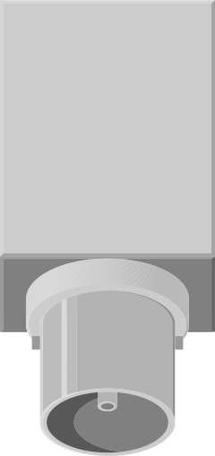
The BNC (Bayonet Neill-Concelman) connector is a type of coaxial connector widely used for radio frequency (RF) connections. It is commonly found in video, audio, and networking applications, as well as in test and measurement equipment. The BNC connector is characterized by its bayonet-style locking mechanism, which ensures a secure and reliable connection while allowing for quick and easy coupling and decoupling.
Explore Projects Built with BNC
 Open Project in Cirkit Designer
 Open Project in Cirkit Designer
 Open Project in Cirkit Designer
 Open Project in Cirkit Designer
Explore Projects Built with BNC
Open Project in Cirkit DesignerOpen Project in Cirkit DesignerOpen Project in Cirkit DesignerOpen Project in Cirkit DesignerCommon Applications and Use Cases
- Video Transmission: Used in CCTV systems, broadcast equipment, and video monitors.
- Audio Applications: Found in professional audio equipment for signal transmission.
- Test and Measurement: Commonly used in oscilloscopes, signal generators, and spectrum analyzers.
- Networking: Utilized in older Ethernet networks (10BASE2) and RF communication systems.
- Laboratory Equipment: Frequently used in research and development setups for signal testing.
Technical Specifications
Key Technical Details
- Impedance: 50 ohms or 75 ohms (depending on the application)
- Frequency Range: Up to 4 GHz (typical for high-quality connectors)
- Voltage Rating: 500 V RMS (typical)
- Coupling Mechanism: Bayonet-style locking
- Material: Brass or zinc alloy with nickel or silver plating
- Connector Type: Male and female (plug and jack)
- Cable Compatibility: Coaxial cables such as RG-58, RG-59, and RG-6
Pin Configuration and Descriptions
The BNC connector does not have traditional "pins" like other electronic components. Instead, it consists of the following key parts:
| Part | Description |
|---|---|
| Center Pin | Carries the signal (positive or active conductor). |
| Outer Shield | Provides grounding and shielding to prevent interference and signal loss. |
| Bayonet Lock | Ensures a secure connection by twisting and locking the connector in place. |
Usage Instructions
How to Use the BNC Connector in a Circuit
- Select the Appropriate Connector: Choose a BNC connector with the correct impedance (50 ohms or 75 ohms) based on your application.
- Prepare the Coaxial Cable:
- Strip the coaxial cable to expose the center conductor and shield.
- Ensure the cable length matches the connector's specifications.
- Attach the Connector:
- Insert the center conductor into the connector's pin.
- Secure the shield to the connector's outer shell using crimping or soldering.
- Connect to the Device:
- Align the BNC connector with the device's port.
- Push the connector in and twist it clockwise to lock it in place.
- Test the Connection:
- Verify the signal transmission using appropriate test equipment (e.g., an oscilloscope).
Important Considerations and Best Practices
- Impedance Matching: Always use a BNC connector with the correct impedance to avoid signal reflection and loss.
- Cable Selection: Use high-quality coaxial cables compatible with the connector to ensure optimal performance.
- Secure Connections: Ensure the bayonet lock is fully engaged to prevent accidental disconnections.
- Environmental Factors: Use weatherproof connectors or covers for outdoor applications to protect against moisture and corrosion.
- Avoid Over-Tightening: Do not apply excessive force when locking the connector, as this may damage the bayonet mechanism.
Example: Connecting a BNC Connector to an Arduino UNO
While the BNC connector itself is not directly connected to an Arduino UNO, it can be used to interface RF signals or analog signals with the Arduino through additional circuitry. Below is an example of reading an analog signal from a BNC connector using an Arduino UNO:
// Example: Reading an analog signal from a BNC connector using Arduino UNO
// Ensure the BNC connector is connected to an appropriate signal source
// and the signal is within the Arduino's input voltage range (0-5V).

const int bncPin = A0; // Analog pin connected to the BNC signal

void setup() {
  Serial.begin(9600); // Initialize serial communication at 9600 baud
}

void loop() {
  int signalValue = analogRead(bncPin); // Read the analog signal
  float voltage = (signalValue / 1023.0) * 5.0; // Convert to voltage (0-5V range)

  // Print the signal value and voltage to the Serial Monitor
  Serial.print("Signal Value: ");
  Serial.print(signalValue);
  Serial.print(" | Voltage: ");
  Serial.println(voltage);

  delay(500); // Wait for 500ms before the next reading
}
Troubleshooting and FAQs
Common Issues and Solutions
| Issue | Solution |
|---|---|
| Loose connection or intermittent signal | Ensure the bayonet lock is fully engaged and the connector is properly seated. |
| Signal loss or interference | Check for impedance mismatch and use high-quality coaxial cables. |
| Corrosion or damage to the connector | Replace the connector or use weatherproof versions for outdoor applications. |
| Difficulty attaching the connector | Verify that the cable is properly prepared and matches the connector type. |
| No signal detected on Arduino | Ensure the signal voltage is within the Arduino's input range (0-5V). |
FAQs
Can I use a 50-ohm BNC connector with a 75-ohm cable?
- While it is possible, it is not recommended as it may cause signal reflection and loss. Always match the impedance of the connector and cable.
What is the maximum frequency a BNC connector can handle?
- High-quality BNC connectors can handle frequencies up to 4 GHz, but this depends on the specific model and manufacturer.
How do I protect BNC connectors in outdoor environments?
- Use weatherproof connectors or protective covers to shield them from moisture, dust, and corrosion.
Can I use a BNC connector for power transmission?
- BNC connectors are not designed for power transmission and should only be used for signal transmission.
What tools are needed to attach a BNC connector to a cable?
- You may need a coaxial cable stripper, crimping tool, and soldering iron (if soldering is required).
By following this documentation, users can effectively utilize BNC connectors in their projects and troubleshoot common issues with ease.