Cirkit Designer Logo
Cirkit Designer
Your all-in-one circuit design IDE
Home / 
Component Documentation

How to Use Adafruit ADXL326: Examples, Pinouts, and Specs

Image of Adafruit ADXL326
Cirkit Designer LogoDesign with Adafruit ADXL326 in Cirkit Designer

Introduction

The Adafruit ADXL326 is a small, thin, low-power, triple-axis accelerometer with signal conditioned voltage outputs. It is capable of measuring acceleration up to ±16 g. It is designed to measure the static acceleration of gravity in tilt-sensing applications, as well as dynamic acceleration resulting from motion, shock, or vibration. Common applications include:

  • Motion detection (e.g., tap detection, free-fall detection)
  • Orientation sensing (e.g., portrait/landscape detection)
  • Vibration analysis in industrial applications
  • Gaming and pointing devices
  • Fitness and health monitoring devices

Explore Projects Built with Adafruit ADXL326

Use Cirkit Designer to design, explore, and prototype these projects online. Some projects support real-time simulation. Click "Open Project" to start designing instantly!
Arduino UNO and ADXL345 Accelerometer Data Logger
Image of Accelerometer ADXL345 Circuit Diagram: A project utilizing Adafruit ADXL326 in a practical application
This circuit features an Arduino UNO microcontroller interfaced with an Adafruit ADXL345 accelerometer for motion detection, powered by two parallel-connected 18650 Li-ion batteries. The accelerometer communicates with the Arduino over I2C, and the system is designed for further code development to utilize the motion sensing capabilities.
Cirkit Designer LogoOpen Project in Cirkit Designer
Arduino Mega 2560 Multi-Sensor Data Logger with I2C Multiplexer
Image of Gesamt Schaltplan: A project utilizing Adafruit ADXL326 in a practical application
This circuit uses an Arduino Mega 2560 to interface with multiple sensors, including an Adafruit ADXL326 accelerometer, a pressure transducer, and two MLX90614 IR temperature sensors connected via an Adafruit TCA9548A I2C multiplexer. The Arduino reads data from these sensors and outputs the values to the Serial Monitor.
Cirkit Designer LogoOpen Project in Cirkit Designer
Arduino UNO with Adafruit ADXL345 Accelerometer Data Logger
Image of ADXL345: A project utilizing Adafruit ADXL326 in a practical application
This circuit connects an Arduino UNO microcontroller with an Adafruit ADXL345 accelerometer sensor. The Arduino powers the sensor, communicates with it via I2C (using pins A4 and A5 for SDA and SCL respectively), and runs a program to read and output the acceleration data in three axes. The purpose of the circuit is to measure acceleration and provide real-time data for analysis or further processing.
Cirkit Designer LogoOpen Project in Cirkit Designer
ESP32-Based 3-Axis Accelerometer Data Logger
Image of adxl337: A project utilizing Adafruit ADXL326 in a practical application
This circuit connects an ESP32 microcontroller to an Adafruit ADXL377 accelerometer. The ESP32 reads acceleration data along the X, Y, and Z axes from the ADXL377 via its D32, D33, and D34 pins, respectively. The circuit is likely intended for motion or orientation sensing applications, with the ESP32 processing and possibly transmitting the accelerometer data for further use.
Cirkit Designer LogoOpen Project in Cirkit Designer

Explore Projects Built with Adafruit ADXL326

Use Cirkit Designer to design, explore, and prototype these projects online. Some projects support real-time simulation. Click "Open Project" to start designing instantly!
Image of Accelerometer ADXL345 Circuit Diagram: A project utilizing Adafruit ADXL326 in a practical application
Arduino UNO and ADXL345 Accelerometer Data Logger
This circuit features an Arduino UNO microcontroller interfaced with an Adafruit ADXL345 accelerometer for motion detection, powered by two parallel-connected 18650 Li-ion batteries. The accelerometer communicates with the Arduino over I2C, and the system is designed for further code development to utilize the motion sensing capabilities.
Cirkit Designer LogoOpen Project in Cirkit Designer
Image of Gesamt Schaltplan: A project utilizing Adafruit ADXL326 in a practical application
Arduino Mega 2560 Multi-Sensor Data Logger with I2C Multiplexer
This circuit uses an Arduino Mega 2560 to interface with multiple sensors, including an Adafruit ADXL326 accelerometer, a pressure transducer, and two MLX90614 IR temperature sensors connected via an Adafruit TCA9548A I2C multiplexer. The Arduino reads data from these sensors and outputs the values to the Serial Monitor.
Cirkit Designer LogoOpen Project in Cirkit Designer
Image of ADXL345: A project utilizing Adafruit ADXL326 in a practical application
Arduino UNO with Adafruit ADXL345 Accelerometer Data Logger
This circuit connects an Arduino UNO microcontroller with an Adafruit ADXL345 accelerometer sensor. The Arduino powers the sensor, communicates with it via I2C (using pins A4 and A5 for SDA and SCL respectively), and runs a program to read and output the acceleration data in three axes. The purpose of the circuit is to measure acceleration and provide real-time data for analysis or further processing.
Cirkit Designer LogoOpen Project in Cirkit Designer
Image of adxl337: A project utilizing Adafruit ADXL326 in a practical application
ESP32-Based 3-Axis Accelerometer Data Logger
This circuit connects an ESP32 microcontroller to an Adafruit ADXL377 accelerometer. The ESP32 reads acceleration data along the X, Y, and Z axes from the ADXL377 via its D32, D33, and D34 pins, respectively. The circuit is likely intended for motion or orientation sensing applications, with the ESP32 processing and possibly transmitting the accelerometer data for further use.
Cirkit Designer LogoOpen Project in Cirkit Designer

Technical Specifications

Key Technical Details

  • Power Supply: 1.8V to 3.6V
  • Sensitivity: 57 mV/g at 3.3V (typical)
  • Measurement Range: ±16 g
  • Bandwidth: Up to 1600 Hz
  • Operating Temperature: -40°C to +85°C
  • Low Power: 350 µA (typical)

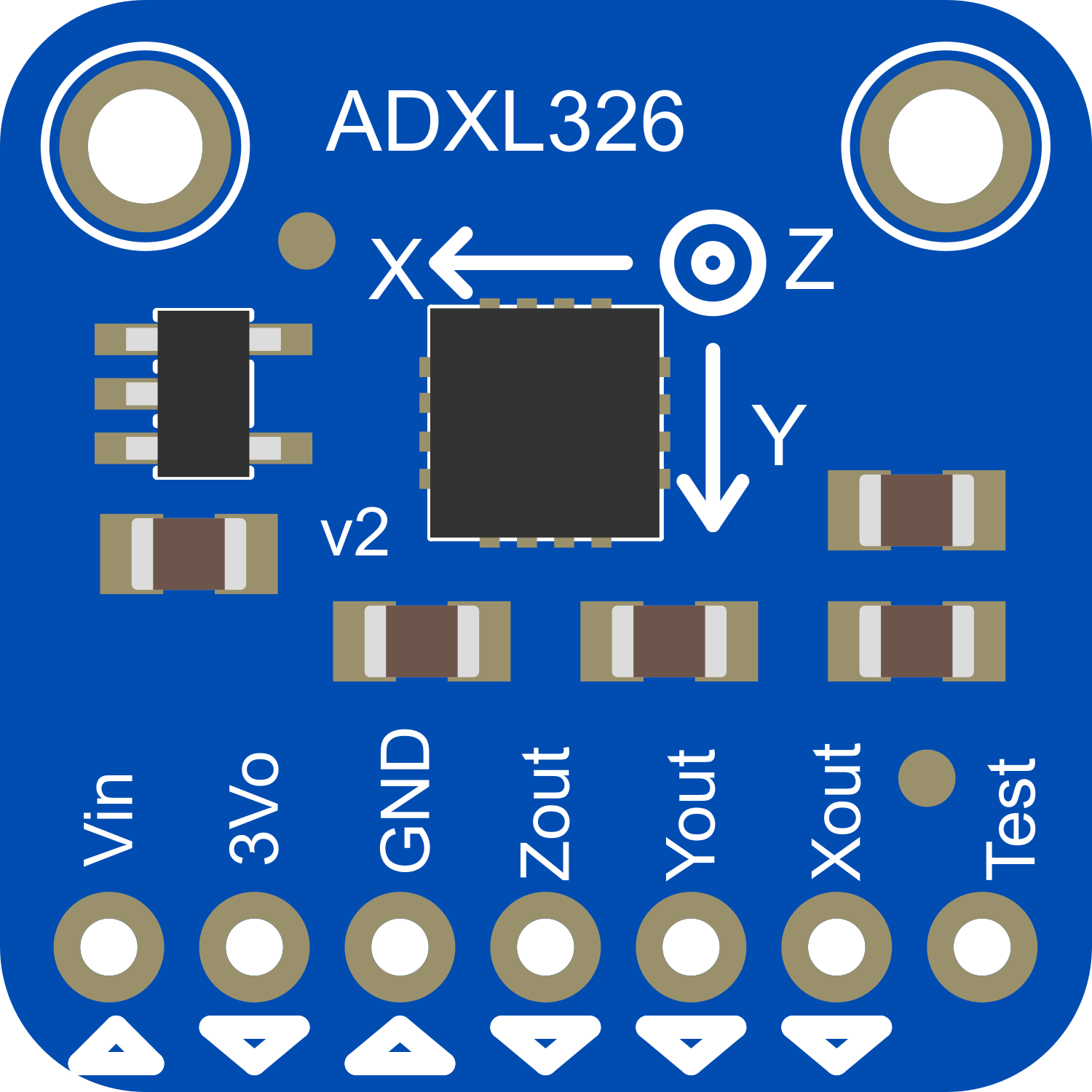
Pin Configuration and Descriptions

Pin Number Name Description
1 VCC Power supply (1.8V to 3.6V)
2 GND Ground connection
3 XOUT Analog voltage output for X-axis
4 YOUT Analog voltage output for Y-axis
5 ZOUT Analog voltage output for Z-axis
6 ST Self-test pin (leave unconnected if not used)

Usage Instructions

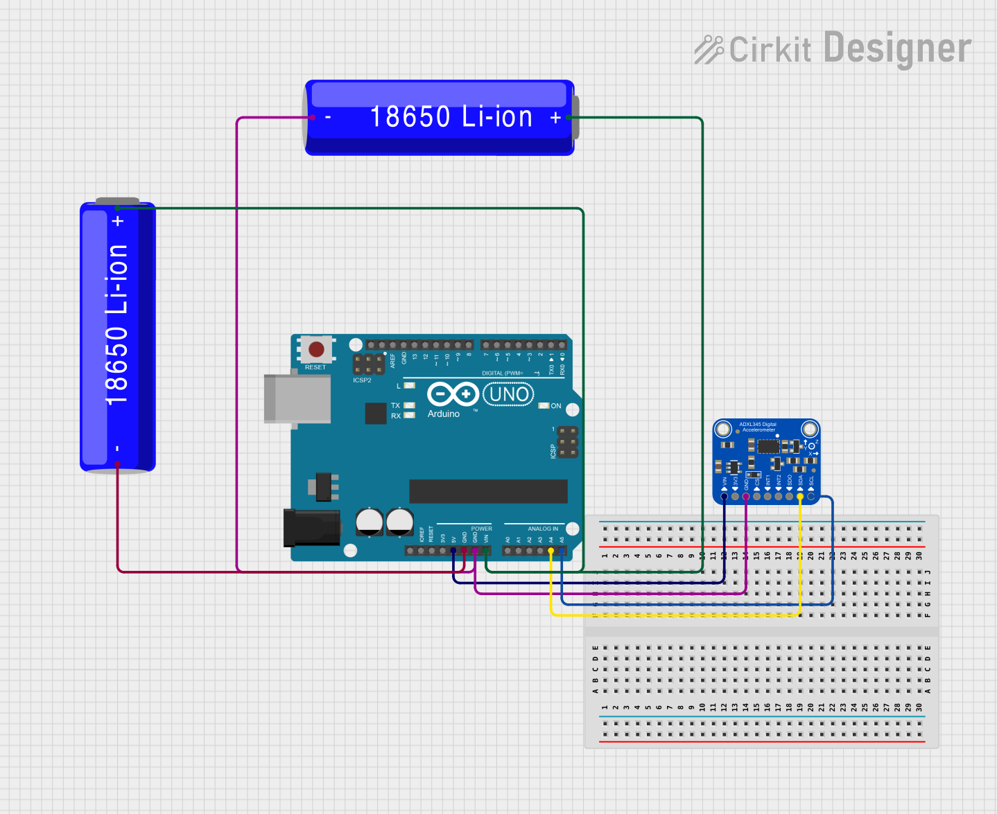
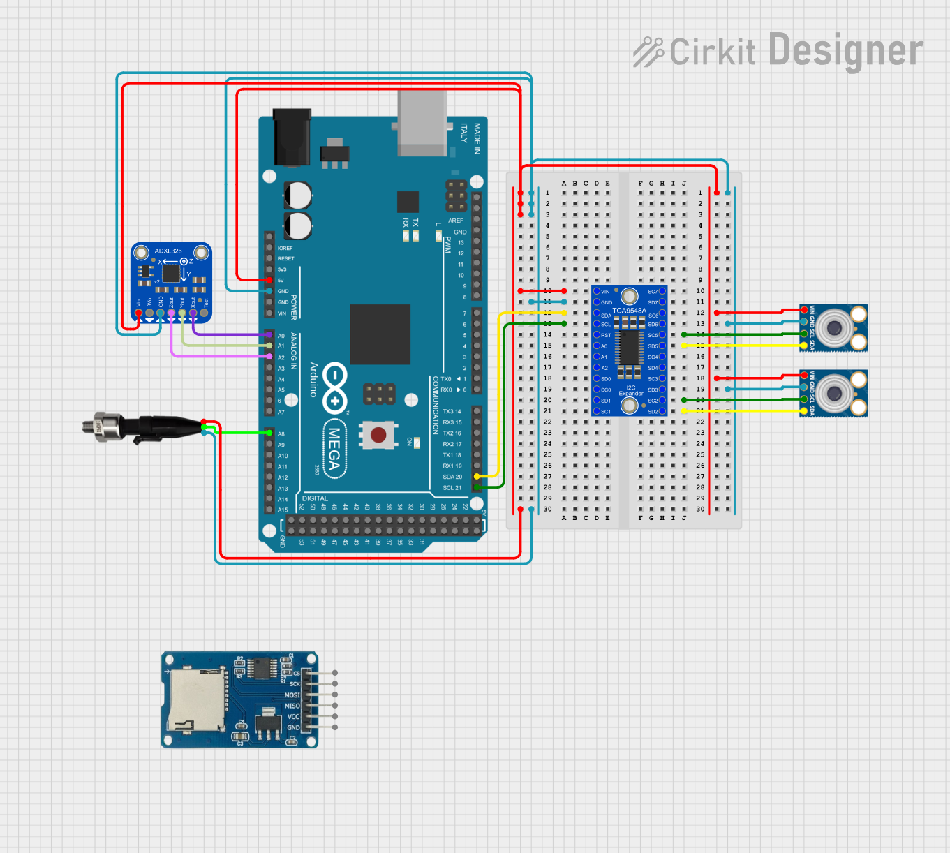
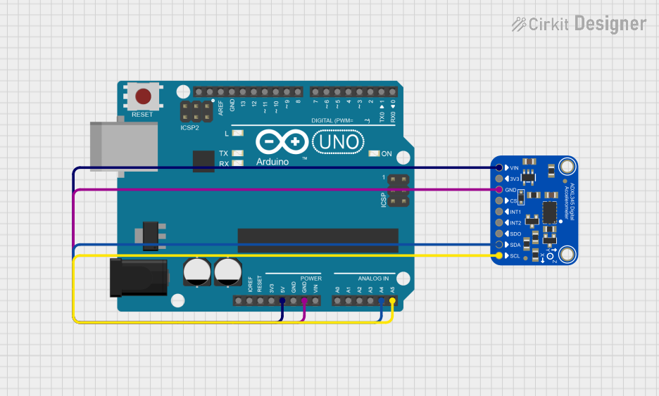
Integration with a Circuit

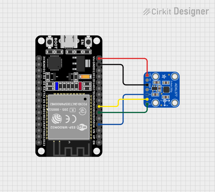
To use the ADXL326 in a circuit:

  1. Connect VCC to a power supply between 1.8V and 3.6V.
  2. Connect GND to the ground of your system.
  3. Connect XOUT, YOUT, and ZOUT to analog inputs on your microcontroller, such as an Arduino UNO.

Best Practices

  • Ensure that the power supply is stable and within the specified voltage range.
  • Use decoupling capacitors close to the VCC and GND pins to minimize power supply noise.
  • Avoid physical stress and overheating during soldering to prevent damage to the sensor.
  • Calibrate the sensor in your application to account for any system-level inaccuracies.

Example Code for Arduino UNO

// Include the Arduino Wire library for I2C
#include <Wire.h>

// ADXL326 outputs are analog and need to be read using analog pins
const int xPin = A0;
const int yPin = A1;
const int zPin = A2;

void setup() {
  // Initialize serial communication at 9600 baud rate
  Serial.begin(9600);
}

void loop() {
  // Read the analog values from the accelerometer
  int xValue = analogRead(xPin);
  int yValue = analogRead(yPin);
  int zValue = analogRead(zPin);

  // Convert the analog values to acceleration in g's
  float xG = (xValue - 512) * (16.0 / 1024.0);
  float yG = (yValue - 512) * (16.0 / 1024.0);
  float zG = (zValue - 512) * (16.0 / 1024.0);

  // Print the acceleration values to the serial monitor
  Serial.print("X: ");
  Serial.print(xG);
  Serial.print("g, Y: ");
  Serial.print(yG);
  Serial.print("g, Z: ");
  Serial.print(zG);
  Serial.println("g");

  // Delay before the next reading
  delay(100);
}

Troubleshooting and FAQs

Common Issues

  • Inaccurate Readings: Ensure that the accelerometer is properly calibrated and that the analog pins are correctly connected.
  • No Output: Check the power supply and connections to the VCC and GND pins. Ensure that the board is not damaged.
  • Intermittent Signals: Verify that there are no loose connections and that the solder joints are solid.

FAQs

Q: Can the ADXL326 be used with a 5V system? A: While the ADXL326 is rated for 1.8V to 3.6V, a logic level converter should be used when interfacing with a 5V system.

Q: How can I improve the accuracy of the sensor? A: Calibration is key. Perform a calibration routine at startup and consider implementing a filtering algorithm to smooth out the data.

Q: What is the purpose of the ST pin? A: The ST pin is used for self-testing the sensor. When activated, it can help verify that the sensor is functioning correctly.

Q: How do I interpret the analog output values? A: The output is proportional to the acceleration measured. You'll need to convert the analog readings to g's using the sensitivity factor provided in the technical specifications.

For further assistance, consult the Adafruit ADXL326 datasheet and additional resources provided by Adafruit.