How to Use AD8232: Examples, Pinouts, and Specs
Introduction
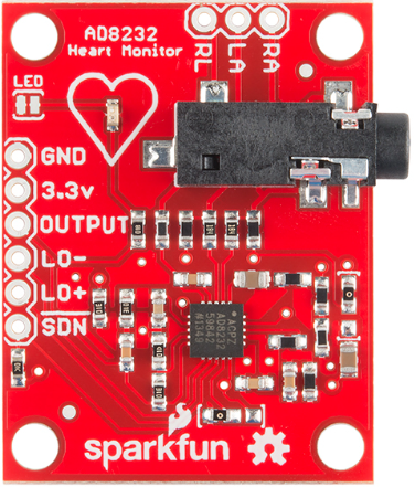
The AD8232 is a low-power, single-lead electrocardiogram (ECG) amplifier manufactured by Analog Devices (Part ID: AD8232ACPZ-R7). It is specifically designed for portable medical devices, enabling the amplification of small bioelectric signals from the heart while filtering out noise. This makes it ideal for heart rate monitoring, fitness tracking, and other biomedical applications.
Explore Projects Built with AD8232
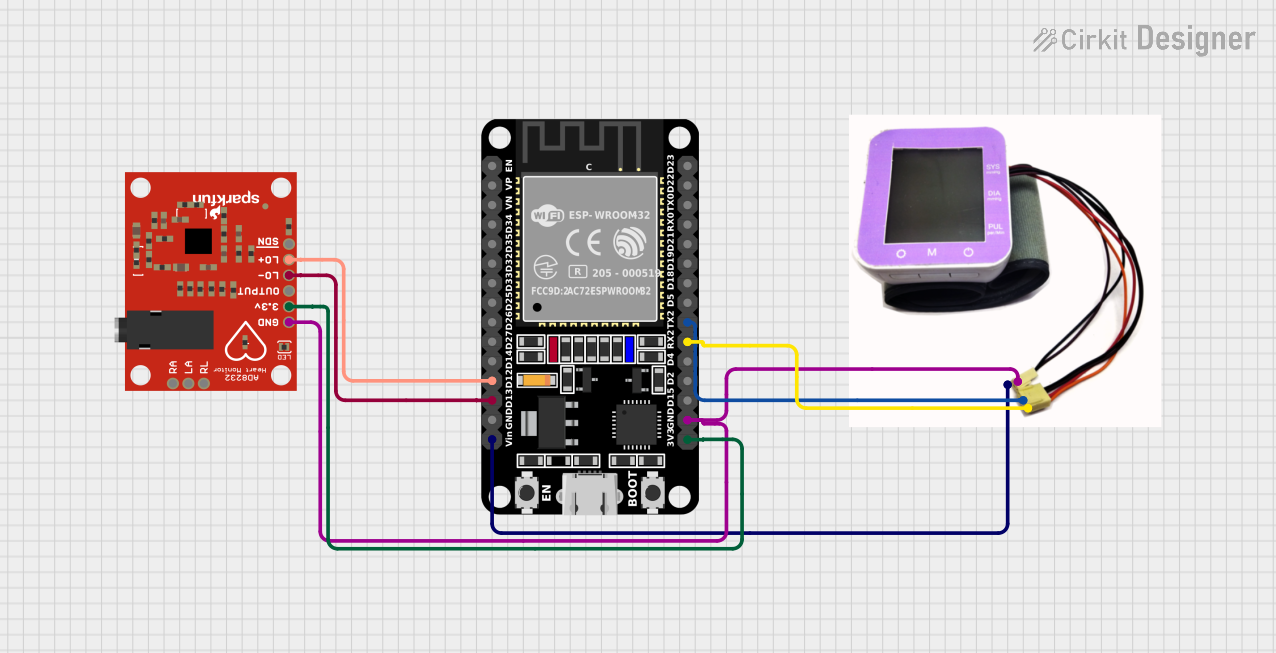
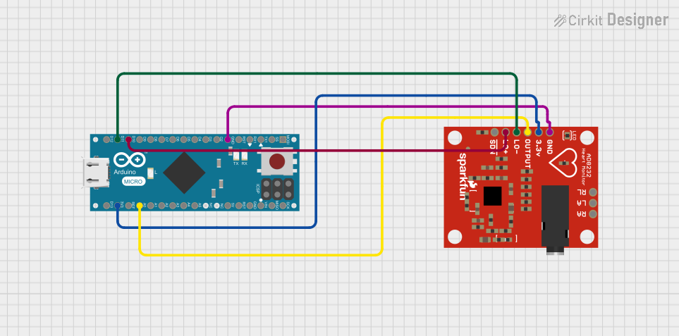
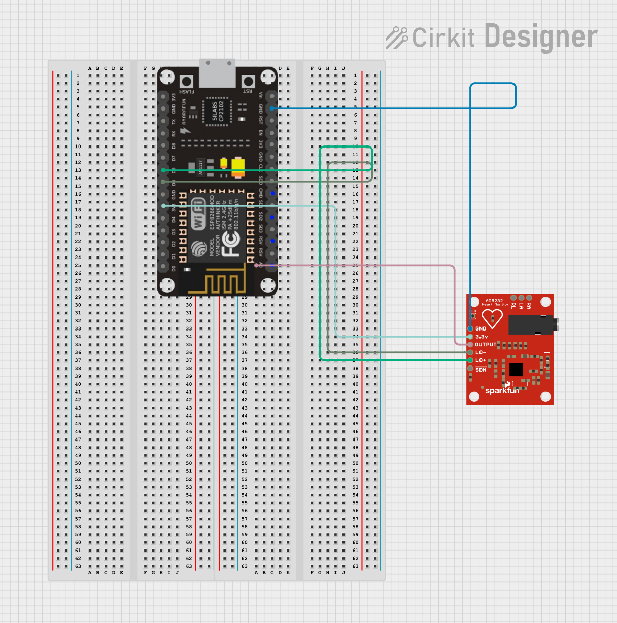
Explore Projects Built with AD8232
Common Applications
- Wearable heart rate monitors
- Fitness and activity trackers
- Portable ECG devices
- Patient monitoring systems
- Biomedical research and prototyping
Technical Specifications
Key Technical Details
| Parameter | Value |
|---|---|
| Supply Voltage Range | 2.0 V to 3.5 V |
| Supply Current | 170 µA (typical) |
| Input Voltage Range | 0 V to (V+ - 1.0 V) |
| Gain | Programmable (26 to 1000) |
| Bandwidth | Configurable (0.5 Hz to 40 Hz for ECG) |
| Output Voltage Range | 0.05 V to (V+ - 0.05 V) |
| Operating Temperature Range | -40°C to +85°C |
| Package Type | 20-lead LFCSP (4 mm × 4 mm) |
Pin Configuration and Descriptions
The AD8232 is available in a 20-lead LFCSP package. Below is the pin configuration and description:
| Pin Number | Pin Name | Description |
|---|---|---|
| 1 | REFOUT | Reference voltage output. Used for biasing the input signal. |
| 2 | REFIN | Reference voltage input. Sets the internal reference voltage. |
| 3 | +IN | Non-inverting input for the instrumentation amplifier. |
| 4 | -IN | Inverting input for the instrumentation amplifier. |
| 5 | RLD | Right leg drive output. Used for patient biasing and noise cancellation. |
| 6 | LO+ | Leads-off detection positive input. |
| 7 | LO- | Leads-off detection negative input. |
| 8 | OUT | Output of the amplified and filtered ECG signal. |
| 9 | SDN | Shutdown pin. Pull low to disable the device and reduce power consumption. |
| 10 | GND | Ground connection. |
| 11 | V+ | Positive supply voltage. |
| 12-20 | NC | No connection. Leave these pins unconnected. |
Usage Instructions
How to Use the AD8232 in a Circuit
- Power Supply: Connect the AD8232 to a stable power supply within the range of 2.0 V to 3.5 V. Ensure proper decoupling capacitors are placed near the power pins to reduce noise.
- Input Connections: Connect the electrodes to the +IN and -IN pins. Use high-quality electrodes to ensure accurate signal acquisition.
- Reference Voltage: Set the reference voltage using the REFIN pin. Typically, this is set to half the supply voltage (V+/2) for optimal performance.
- Output Signal: The amplified and filtered ECG signal is available at the OUT pin. This can be connected to an ADC (Analog-to-Digital Converter) for further processing.
- Leads-Off Detection: Use the LO+ and LO- pins to detect if the electrodes are properly connected to the patient.
- Right Leg Drive (RLD): Connect the RLD pin to the patient’s right leg for biasing and noise cancellation.
Important Considerations and Best Practices
- Electrode Placement: Ensure proper placement of electrodes on the body to minimize motion artifacts and noise.
- Filtering: Configure the internal filters to match the desired bandwidth for ECG signals (typically 0.5 Hz to 40 Hz).
- Leads-Off Detection: Implement leads-off detection in your circuit to alert users when electrodes are disconnected.
- Shutdown Mode: Use the SDN pin to reduce power consumption when the device is not in use.
- PCB Design: Use a clean PCB layout with proper grounding to minimize noise and interference.
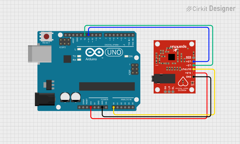
Example: Connecting the AD8232 to an Arduino UNO
Below is an example of how to interface the AD8232 with an Arduino UNO to read ECG signals:
Circuit Connections
- Connect the OUT pin of the AD8232 to the A0 pin of the Arduino UNO.
- Connect the GND pin of the AD8232 to the GND pin of the Arduino UNO.
- Connect the V+ pin of the AD8232 to the 3.3V pin of the Arduino UNO.
Arduino Code
// AD8232 ECG Signal Reader
// Reads the ECG signal from the AD8232 and displays it on the Serial Monitor.

const int ecgPin = A0; // Analog pin connected to the AD8232 OUT pin

void setup() {
  Serial.begin(9600); // Initialize serial communication at 9600 baud
  pinMode(ecgPin, INPUT); // Set the ECG pin as input
}

void loop() {
  int ecgValue = analogRead(ecgPin); // Read the ECG signal
  Serial.println(ecgValue); // Print the ECG value to the Serial Monitor

  delay(10); // Small delay to control the sampling rate
}
Notes:
- Use a serial plotter (available in the Arduino IDE) to visualize the ECG waveform.
- Ensure proper grounding between the AD8232 and Arduino UNO to avoid noise.
Troubleshooting and FAQs
Common Issues and Solutions
No Output Signal:
- Verify that the power supply is within the specified range (2.0 V to 3.5 V).
- Check the connections to the electrodes and ensure they are properly placed on the body.
- Confirm that the reference voltage (REFIN) is correctly set.
High Noise in the Output:
- Ensure proper grounding and shielding of the circuit.
- Use high-quality electrodes and cables to minimize noise.
- Check for motion artifacts and ensure the patient remains still during measurement.
Leads-Off Detection Not Working:
- Verify the connections to the LO+ and LO- pins.
- Ensure the leads-off detection circuit is properly configured.
Device Overheating:
- Check for excessive supply voltage or incorrect connections.
- Ensure the device is operating within the specified temperature range (-40°C to +85°C).
FAQs
Q: Can the AD8232 be used for multi-lead ECG systems?
A: The AD8232 is designed for single-lead ECG applications. For multi-lead systems, additional amplifiers or specialized ICs are required.
Q: What type of electrodes should I use with the AD8232?
A: Use high-quality disposable or reusable ECG electrodes with good skin contact to ensure accurate signal acquisition.
Q: How do I configure the bandwidth of the AD8232?
A: The bandwidth can be configured by selecting appropriate external resistors and capacitors for the internal filters. Refer to the AD8232 datasheet for detailed calculations.
Q: Can I power the AD8232 with a 5V supply?
A: No, the maximum supply voltage for the AD8232 is 3.5V. Exceeding this limit may damage the device.
Q: Is the AD8232 suitable for continuous monitoring?
A: Yes, the AD8232 is designed for low-power operation, making it suitable for continuous monitoring in portable devices.