
How to Use voltage sensor : Examples, Pinouts, and Specs
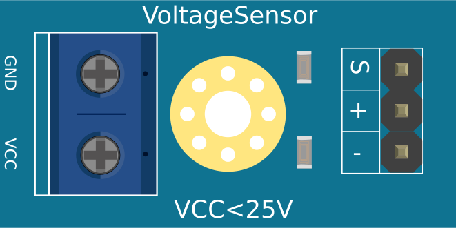
 Design with voltage sensor in Cirkit Designer
Introduction
A voltage sensor is a device that detects and measures the voltage level in a circuit, providing feedback for monitoring and control purposes. It is commonly used in applications where voltage monitoring is critical, such as battery management systems, power supply monitoring, and industrial automation. Voltage sensors are essential for ensuring the safety and efficiency of electrical systems by providing real-time voltage data.
Explore Projects Built with voltage sensor
 Open Project in Cirkit Designer
 Open Project in Cirkit Designer
 Open Project in Cirkit Designer
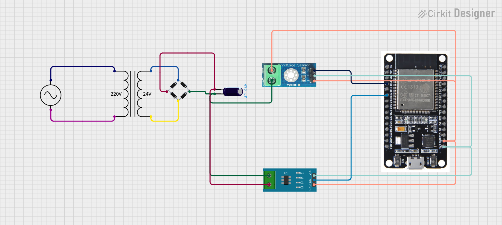 Open Project in Cirkit Designer
Explore Projects Built with voltage sensor
Open Project in Cirkit DesignerOpen Project in Cirkit DesignerOpen Project in Cirkit DesignerOpen Project in Cirkit DesignerCommon Applications:
- Battery voltage monitoring in renewable energy systems
- Power supply regulation in electronic devices
- Industrial automation and control systems
- Overvoltage and undervoltage protection circuits
- IoT devices for remote voltage monitoring
Technical Specifications
Below are the general technical specifications for a typical voltage sensor module (e.g., a voltage divider-based sensor like the LM2596 or similar):
| Parameter | Value |
|---|---|
| Input Voltage Range | 0V to 25V (varies by model) |
| Output Voltage Range | 0V to 5V (scaled for ADC input) |
| Measurement Accuracy | ±1% (typical) |
| Operating Voltage | 3.3V or 5V (depending on module) |
| Interface | Analog Output |
| Dimensions | ~30mm x 15mm x 10mm |
Pin Configuration and Descriptions
| Pin Name | Description |
|---|---|
| VCC | Power supply input (3.3V or 5V) |
| GND | Ground connection |
| VIN+ | Positive voltage input to be measured |
| VIN- | Negative voltage input (usually GND) |
| VOUT | Analog voltage output (scaled for ADC) |
Usage Instructions
How to Use the Voltage Sensor in a Circuit
- Power the Sensor: Connect the
VCCpin to a 3.3V or 5V power source, depending on the module's specifications. Connect theGNDpin to the ground of your circuit. - Connect the Voltage to Be Measured: Attach the positive terminal of the voltage source to the
VIN+pin and the negative terminal to theVIN-pin. - Read the Output Voltage: The
VOUTpin provides an analog voltage proportional to the input voltage. This output can be connected to an ADC (Analog-to-Digital Converter) pin of a microcontroller, such as an Arduino UNO, for further processing.
Important Considerations and Best Practices
- Voltage Range: Ensure the input voltage does not exceed the sensor's maximum rated voltage (e.g., 25V). Exceeding this limit may damage the sensor.
- Scaling Factor: Most voltage sensors use a voltage divider circuit. For example, if the input voltage range is 0-25V and the output range is 0-5V, the scaling factor is 5:1. Multiply the ADC reading by this factor to calculate the actual input voltage.
- Calibration: For accurate measurements, calibrate the sensor using a known voltage source and adjust the scaling factor if necessary.
- Noise Reduction: Use decoupling capacitors near the sensor to reduce noise in the output signal.
Example: Using a Voltage Sensor with Arduino UNO
Below is an example of how to use a voltage sensor with an Arduino UNO to measure and display the input voltage:
// Define the analog pin connected to the voltage sensor's VOUT pin
const int sensorPin = A0;

// Define the scaling factor (e.g., 5:1 for a 25V sensor)
const float scalingFactor = 5.0;

// Variable to store the ADC reading
int sensorValue = 0;

// Variable to store the calculated voltage
float voltage = 0.0;

void setup() {
  // Initialize serial communication for debugging
  Serial.begin(9600);
}

void loop() {
  // Read the analog value from the sensor
  sensorValue = analogRead(sensorPin);

  // Convert the ADC value to a voltage (0-5V range)
  float sensorVoltage = sensorValue * (5.0 / 1023.0);

  // Scale the voltage to the actual input voltage
  voltage = sensorVoltage * scalingFactor;

  // Print the voltage to the Serial Monitor
  Serial.print("Input Voltage: ");
  Serial.print(voltage);
  Serial.println(" V");

  // Wait for 1 second before the next reading
  delay(1000);
}
Notes:
- Replace
scalingFactorwith the appropriate value for your sensor. - Ensure the Arduino's ADC reference voltage matches the sensor's output range (e.g., 5V).
Troubleshooting and FAQs
Common Issues and Solutions
Incorrect Voltage Readings:
- Cause: Incorrect scaling factor or calibration.
- Solution: Verify the scaling factor and calibrate the sensor using a known voltage source.
No Output Voltage:
- Cause: Improper wiring or insufficient power supply.
- Solution: Double-check all connections and ensure the sensor is powered correctly.
Fluctuating Readings:
- Cause: Electrical noise or unstable input voltage.
- Solution: Add decoupling capacitors near the sensor and ensure a stable input voltage.
Sensor Overheating:
- Cause: Input voltage exceeds the sensor's maximum rating.
- Solution: Ensure the input voltage is within the specified range.
FAQs
Q1: Can I use the voltage sensor to measure AC voltage?
A1: No, most voltage sensors are designed for DC voltage only. To measure AC voltage, use a dedicated AC voltage sensor or a rectifier circuit.
Q2: What is the maximum voltage I can measure with this sensor?
A2: The maximum voltage depends on the sensor model. For example, a typical sensor may measure up to 25V. Check the datasheet for your specific sensor.
Q3: Can I connect the sensor directly to a microcontroller?
A3: Yes, the sensor's VOUT pin provides an analog voltage that can be read by the ADC pin of a microcontroller, such as an Arduino.
Q4: How do I improve measurement accuracy?
A4: Use a high-resolution ADC, calibrate the sensor, and minimize noise in the circuit.
By following this documentation, you can effectively use a voltage sensor in your projects for accurate voltage monitoring and control.