How to Use PN532: Examples, Pinouts, and Specs
Introduction
The PN532, manufactured by NXP Semiconductors, is a highly versatile NFC (Near Field Communication) controller. It supports multiple NFC modes, including reader/writer, card emulation, and peer-to-peer communication. This makes it an ideal choice for a wide range of applications, such as:
- Contactless payment systems
- Access control and authentication
- Data exchange between NFC-enabled devices
- Smart posters and NFC tags
- IoT applications requiring short-range wireless communication
The PN532 is widely used due to its robust functionality, ease of integration, and compatibility with various microcontrollers, including Arduino.
Explore Projects Built with PN532


Explore Projects Built with PN532
Technical Specifications
The PN532 is designed to meet the needs of modern NFC applications. Below are its key technical specifications:
| Parameter | Value |
|---|---|
| Manufacturer | NXP Semiconductors |
| Part Number | PN532 |
| Operating Voltage | 2.7V to 5.5V |
| Communication Interfaces | I²C, SPI, UART |
| NFC Modes Supported | Reader/Writer, Card Emulation, Peer-to-Peer |
| Operating Frequency | 13.56 MHz |
| Maximum Data Rate | Up to 424 kbps |
| Supported Protocols | ISO/IEC 14443A/B, FeliCa, ISO/IEC 18092 (NFCIP-1) |
| Operating Temperature | -25°C to +85°C |
| Dimensions | Varies depending on the breakout board/module |
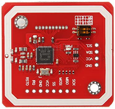
Pin Configuration and Descriptions
The PN532 is typically available as a breakout board or module. Below is a common pin configuration for a PN532 module:
| Pin Name | Description |
|---|---|
| VCC | Power supply input (2.7V to 5.5V) |
| GND | Ground connection |
| SDA | I²C data line (used in I²C communication mode) |
| SCL | I²C clock line (used in I²C communication mode) |
| MOSI | Master Out Slave In (used in SPI communication mode) |
| MISO | Master In Slave Out (used in SPI communication mode) |
| SCK | Serial Clock (used in SPI communication mode) |
| NSS | SPI Chip Select (used in SPI communication mode) |
| RX | UART Receive (used in UART communication mode) |
| TX | UART Transmit (used in UART communication mode) |
| IRQ | Interrupt request output (used for event signaling) |
| RST | Reset pin (used to reset the module) |
Note: The exact pinout may vary depending on the specific PN532 breakout board or module. Always refer to the datasheet or documentation provided with your module.
Usage Instructions
The PN532 can be used in various NFC applications. Below are the steps to integrate and use the PN532 in a circuit:
1. Connecting the PN532 to an Arduino UNO
The PN532 supports multiple communication protocols (I²C, SPI, UART). For simplicity, we'll use the I²C interface in this example.
Wiring Diagram
| PN532 Pin | Arduino UNO Pin |
|---|---|
| VCC | 5V |
| GND | GND |
| SDA | A4 |
| SCL | A5 |
| IRQ | Not connected |
| RST | Digital Pin 2 |
Arduino Code Example
Below is an example of how to use the PN532 with an Arduino UNO to read an NFC tag:
#include <Wire.h>
#include <Adafruit_PN532.h>

// Define the reset and IRQ pins
#define RST_PIN 2
#define IRQ_PIN 3

// Create an instance of the Adafruit_PN532 library
Adafruit_PN532 nfc(RST_PIN, IRQ_PIN);

void setup() {
  Serial.begin(9600);
  Serial.println("Initializing PN532...");

  // Initialize the PN532
  nfc.begin();

  // Check if the PN532 is connected
  uint32_t versiondata = nfc.getFirmwareVersion();
  if (!versiondata) {
    Serial.println("Didn't find PN532 board");
    while (1); // Halt execution if the board is not found
  }

  // Display firmware version
  Serial.print("Found PN532 with firmware version: ");
  Serial.print((versiondata >> 16) & 0xFF, HEX);
  Serial.print('.');
  Serial.println((versiondata >> 8) & 0xFF, HEX);

  // Configure the board to read NFC tags
  nfc.SAMConfig();
  Serial.println("Waiting for an NFC tag...");
}

void loop() {
  uint8_t success;
  uint8_t uid[] = { 0, 0, 0, 0, 0, 0, 0 }; // Buffer to store the UID
  uint8_t uidLength; // Length of the UID

  // Try to read an NFC tag
  success = nfc.readPassiveTargetID(PN532_MIFARE_ISO14443A, uid, &uidLength);

  if (success) {
    Serial.println("NFC tag detected!");
    Serial.print("UID Length: "); Serial.print(uidLength, DEC); Serial.println(" bytes");
    Serial.print("UID Value: ");
    for (uint8_t i = 0; i < uidLength; i++) {
      Serial.print(" 0x"); Serial.print(uid[i], HEX);
    }
    Serial.println();
    delay(1000); // Wait 1 second before scanning again
  }
}
2. Important Considerations
- Power Supply: Ensure the PN532 module is powered within its operating voltage range (2.7V to 5.5V).
- Communication Protocol: Select the appropriate communication protocol (I²C, SPI, or UART) based on your application and microcontroller.
- Antenna Placement: Avoid placing the PN532 module near metal objects, as they can interfere with NFC communication.
- Libraries: Use reliable libraries, such as the Adafruit_PN532 library, to simplify development.
Troubleshooting and FAQs
Common Issues and Solutions
PN532 not detected by the microcontroller:
- Ensure the wiring is correct and matches the selected communication protocol.
- Verify that the PN532 module is powered correctly.
- Check if the correct library and initialization settings are used.
NFC tag not detected:
- Ensure the tag is compatible with the PN532 (e.g., ISO/IEC 14443A/B).
- Verify that the tag is within the effective range of the PN532 antenna.
- Avoid interference from nearby metal objects or other electronic devices.
Communication errors:
- Double-check the baud rate and communication settings.
- Ensure pull-up resistors are used for I²C communication if required.
FAQs
Q: Can the PN532 read/write NFC tags?
A: Yes, the PN532 supports both reading and writing NFC tags in reader/writer mode.
Q: What is the maximum range of the PN532?
A: The effective range depends on the antenna design and NFC tag but is typically up to 5 cm.
Q: Can the PN532 be used for peer-to-peer communication?
A: Yes, the PN532 supports peer-to-peer communication as per the NFCIP-1 standard.
Q: Is the PN532 compatible with Arduino?
A: Yes, the PN532 is compatible with Arduino and can be easily integrated using libraries like Adafruit_PN532.
By following this documentation, you can effectively integrate and use the PN532 in your NFC projects.