How to Use LM2596 Buck Converter: Examples, Pinouts, and Specs
Introduction
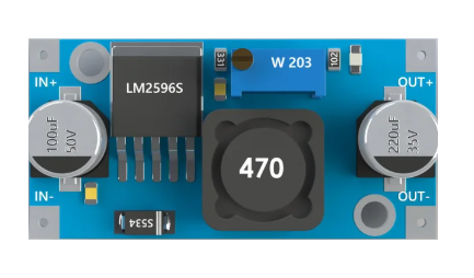
The LM2596 Buck Converter is a step-down voltage regulator designed to efficiently convert a higher input voltage to a lower output voltage. It is widely used in power supply applications due to its high efficiency, ease of use, and ability to handle significant current loads. The LM2596 is ideal for applications requiring a stable and adjustable DC voltage, such as powering microcontrollers, sensors, and other electronic devices.
Explore Projects Built with LM2596 Buck Converter


Explore Projects Built with LM2596 Buck Converter
Common Applications
- Powering microcontrollers (e.g., Arduino, Raspberry Pi)
- Battery charging circuits
- LED drivers
- DC motor controllers
- General-purpose DC-DC voltage regulation
Technical Specifications
The LM2596 Buck Converter is available in both fixed and adjustable output voltage versions. Below are the key technical details:
General Specifications
| Parameter | Value |
|---|---|
| Input Voltage Range | 4.5V to 40V |
| Output Voltage Range | 1.23V to 37V (adjustable version) |
| Output Current | Up to 3A |
| Efficiency | Up to 92% |
| Switching Frequency | 150 kHz |
| Operating Temperature | -40°C to +125°C |
Pin Configuration
The LM2596 is typically available in a 5-pin TO-220 package. Below is the pinout description:
| Pin Number | Pin Name | Description |
|---|---|---|
| 1 | VIN | Input voltage (4.5V to 40V) |
| 2 | Output | Regulated output voltage |
| 3 | Ground | Ground connection |
| 4 | Feedback | Feedback pin for adjustable output voltage |
| 5 | ON/OFF | Enable/disable control (optional, not always used) |
Usage Instructions
How to Use the LM2596 in a Circuit
Connect the Input Voltage (VIN):
Attach the positive terminal of your power source to the VIN pin and the negative terminal to the Ground pin.Set the Output Voltage (Adjustable Version):
- Use a potentiometer or resistor divider connected to the Feedback pin to set the desired output voltage.
- The output voltage can be calculated using the formula:
[ V_{OUT} = V_{REF} \times \left(1 + \frac{R_2}{R_1}\right) ]
where ( V_{REF} ) is typically 1.23V.
Connect the Load:
Attach the positive terminal of your load to the Output pin and the negative terminal to Ground.Enable the Converter (if applicable):
If the ON/OFF pin is available, connect it to a logic HIGH (enable) or LOW (disable) signal.
Important Considerations
- Input Voltage: Ensure the input voltage is at least 1.5V higher than the desired output voltage for proper regulation.
- Heat Dissipation: For high current loads, use a heatsink to prevent overheating.
- Capacitors: Use appropriate input and output capacitors (e.g., 100µF electrolytic) to stabilize the circuit and reduce noise.
- Inductor Selection: Choose an inductor with a current rating higher than the maximum load current.
Example: Using LM2596 with Arduino UNO
Below is an example of how to use the LM2596 to power an Arduino UNO with a 12V input and 5V output.
Circuit Connections
- Connect a 12V DC power source to the VIN and Ground pins of the LM2596.
- Adjust the potentiometer to set the output voltage to 5V.
- Connect the Output pin to the Arduino's 5V pin and Ground to Ground.
Arduino Code Example
// Example code to blink an LED using Arduino UNO powered by LM2596
// Ensure the LM2596 output is set to 5V before connecting to the Arduino

const int ledPin = 13; // Built-in LED pin on Arduino UNO

void setup() {
  pinMode(ledPin, OUTPUT); // Set LED pin as output
}

void loop() {
  digitalWrite(ledPin, HIGH); // Turn the LED on
  delay(1000);               // Wait for 1 second
  digitalWrite(ledPin, LOW);  // Turn the LED off
  delay(1000);               // Wait for 1 second
}
Troubleshooting and FAQs
Common Issues
Output Voltage is Incorrect:
- Cause: Potentiometer not adjusted properly or incorrect resistor values.
- Solution: Recheck the potentiometer or resistor divider settings and adjust as needed.
Overheating:
- Cause: High current load or insufficient heat dissipation.
- Solution: Attach a heatsink to the LM2596 and ensure proper ventilation.
No Output Voltage:
- Cause: Input voltage is too low or the ON/OFF pin is disabled.
- Solution: Verify the input voltage and ensure the ON/OFF pin is enabled (if applicable).
Noise or Instability:
- Cause: Insufficient input/output capacitors or poor PCB layout.
- Solution: Add appropriate capacitors (e.g., 100µF electrolytic and 0.1µF ceramic) and ensure short, thick traces for high-current paths.
FAQs
Q: Can the LM2596 be used for AC input?
A: No, the LM2596 is designed for DC input only. Use a rectifier and filter circuit to convert AC to DC before using the LM2596.
Q: What is the maximum current the LM2596 can handle?
A: The LM2596 can handle up to 3A, but proper heat dissipation is required for high current loads.
Q: Can I use the LM2596 to power a Raspberry Pi?
A: Yes, but ensure the output voltage is set to 5V and the current rating meets the Raspberry Pi's requirements.
Q: Is the LM2596 suitable for battery-powered applications?
A: Yes, it is efficient and can step down voltage from a battery to power lower voltage devices.
By following this documentation, you can effectively use the LM2596 Buck Converter in your projects.